
Instruction manual


P82724 E
Sheet 3 of 9
CAUTION: Disconnect power prior to connecting or disconnecting to either the inputs or the outputs. Failure to disconnect
power when connecting or disconnecting inputs or outputs could cause internal damage.
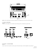
Telephone Paging Input (Figure 1)
: Connect telephone wires to the input screw terminals marked TIP and RING. Set TEL/MIC 1
Switch (on front panel) to TEL position. For Tip and Ring connections to various types of telephone paging access, see Figures 7A,
B & C. NOTE: This input is a transformer isolated, line level input and may be used for applications other than telephone paging
(i.e. tone signaling).
Microphone Inputs (Figure 1)
: Connect balanced low-impedance microphone wires to the input screw terminals marked LO-Z. The
shield must be connected to the GND screw terminals. An unbalanced microphone may be connected to the same screw terminals.
However, one of the two LO-Z terminals for that input must be connected to the adjacent screw terminal marked GND. Install a
jumper wire, between one LO-Z screw terminal and the GND screw terminal.
NOTE: To avoid noise pick-up, the microphone input cable should be a shielded cable, with the shield connected to the input GND
terminal.
MIC 2 is a low impedance (LO-Z) microphone input channel. TEL/MIC 1 is a switch selectable telephone paging, or low impedance
(LO-Z) microphone input channel.
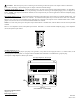
Input Connections
Figure 1.
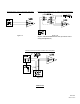
Auxiliary Input (Figure 2)
:
To connect an FM tuner, CD player, tape player, tone generator, or any other line level program source (i.e., mic/line mixer) to the
AUX input jack on the side panel, use a single conductor shielded cable terminated in a standard RCA type phono plug.
AUX input is a high impedance (HI-Z) input channel.
Aux High Impedance (Hi-Z) Input
Figure 2:
(AA-40 Shown - AA-20 Similar)
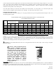
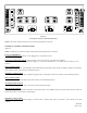
OUTPUT CONNECTIONS:
(Figures 3 & 4)
Referring To Figure 3
: