
Specifications


273 Branchport Avenue • Long Branch, NJ 07740 • (800) 631-2148 • www.wheelockinc.com
WARNING: THESE APPLIANCES WERE TESTED TO THE LISTED OPERATING VOLTAGE LIMITS USING FILTERED (DC) OR UNFILTERED (DC) OR
FULL-WAVE-RECTIFIED (FWR). DO NOT APPLY 80% AND 110% OF THESE VOLTAGE VALUES FOR SYSTEMS OPERATION. THE APPLICATION OF
IMPROPER VOLTAGE MAY RESULT IN DEGRADED OPERATION OR DAMAGE TO THESE PRODUCTS.
WARNING: MAKE SURE THAT ALL FUSES USED ON NAC CIRCUITS ARE RATED TO HANDLE THE MAXIMUM INRUSH OR PEAK CURRENT FOR
ALL APPLIANCES ON THOSE CIRCUITS. FAILURE TO DO THIS MAY RESULT IN LOSS OF POWER TO THE NAC CIRCUIT AND THE FAILURE OF
ALL APPLIANCES ON THAT CIRCUIT TO OPERATE, WHICH COULD RESULT IN PROPERTY DAMAGE AND SERIOUS INJURY OR DEATH TO YOU
AND/OR OTHERS.
The UL Listed “Regulated Voltage Range” is 16-33 VDC or 8-17.5 VDC using either filtered (DC) or unfiltered full-wave rectified (FWR) voltage unless
otherwise noted in this catalog. Check the minimum and maximum output of the power supply and standby battery and subtract the voltage drop from
the circuit wiring resistance to determine the applied voltage to the strobes.
All candela ratings represent minimum effective strobe intensity based on UL 1971.
WARNING: USE STROBES ONLY ON CIRCUITS WITH CONTINUOUSLY APPLIED OPERATING VOLTAGE. DO NOT USE STROBES ON CODED OR
INTERRUPTED CIRCUITS IN WHICH THE APPLIED VOLTAGE IS CYCLED ON AND OFF, AS THE STROBE MAY NOT FLASH.
Wheelock products must be used within their published specifications and must be PROPERLY specified, applied, installed, operated, maintained and
operationally tested in accordance with their installation instructions at the time of installation and at least twice a year or more often and in accordance
with local, state and federal codes, regulations and laws. Specification, application, installation, operation, maintenance, and testing must be performed
by qualified personnel for proper operation in accordance with all of the latest National Fire Protection Association (NFPA), Underwriters’ Laboratories
(UL), National Electrical Code (NEC), Occupation Safety and Health Administration (OSHA), local, state, county, province, district, federal and other
applicable building and fire standards, guidelines, regulations, laws, and codes including, but not limited to, all appendices and amendments
and the
requirements of the local authority having jurisdiction (AHJ).
1. All VFWR voltages in strobe current requirement table are measured with DC volt meter. Multiply VFWR voltage by 1.11 to convert to VRMS.
2 Use the highest value of rated average current to determine the maximum number of strobes and to establish power supplies and wire gauge
requirements. Use the rated peak current or rated inrush current (whichever is higher) to verify fuse requirements.
3. Make sure that the average, peak and inrush currents do not exceed system power supplies or fusing limits. See “Installation Instructions”.
4 The 15/75 cd wall mounted strobes are listed at 15 cd under UL Standard 1971 and meet 75 cd intensity on axis for ADA Guidelines.
5. Read Installation Instructions for the Software Installation and operation of Electronic Access Control Products.
WARNING: CONTACT WHEELOCK FOR THE MOST CURRENT “SPECIFICATION SHEETS”, “INSTALLATION INSTRUCTIONS” AND “GENERAL
INFORMATION” SHEETS ON THESE PRODUCTS. THESE DOCUMENTS UNDERGO PERIODIC CHANGES. IT IS IMPORTANT THAT YOU HAVE
CURRENT INFORMATION ON THESE PRODUCTS. THESE MATERIALS CONTAIN IMPORTANT INFORMATION THAT SHOULD BE READ PRIOR TO
SPECIFYING OR INSTALLING THESE PRODUCTS INCLUDING:
• TOTAL CURRENT REQUIRED BY ALL APPLIANCES CONNECTED TO SYSTEM PRIMARY AND SECONDARY POWER SOURCES.
• FUSE RATINGS ON NAC CIRCUITS TO HANDLE MAXIMUM INRUSH OR PEAK CURRENT FROM ALL APPLIANCES ON
THOSE CIRCUITS.
• COMPOSITE FLASH RATE FROM MULTIPLE STROBES WITHIN A PERSON’S FIELD OF VIEW.
• INSTALLATION OF 110 CANDELA STROBE PRODUCTS IN SLEEPING AREAS.
• INSTALLATION IN OFFICE AREAS AND OTHER SPECIFICATION AND INSTALLATION ISSUES.
• LIMITED WARRANTY CONDITIONS.
WARNING: FAILURE TO COMPLY WITH ANY INSTRUCTIONS, CAUTIONS, AND WARNINGS COULD RESULT IN IMPROPER APPLICATION,
INSTALLATION AND/OR OPERATION OF THESE PRODUCTS IN AN EMERGENCY SITUATION, WHICH COULD RESULT IN PROPERTY DAMAGE,
SERIOUS INJURY OR DEATH TO YOU AND/OR OTHERS.
General & Technical
Notes
NOTE: ALL CAUTIONS AND WARNINGS are identified by the symbol
All warnings are printed in bold capital letters.
Warnings
Specification Notes
Mounting Notes
GENERAL AND TECHNICAL NOTES
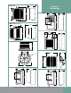
Caution: The mounting option figures show the maximum number of field wires (conductors) that can enter the backbox used with each
mounting option. If these limits are exceeded, there may be insufficient space in the backbox to accommodate the field wires and stresses from the
wires could damage the product.
Although the limits shown for each mounting option comply with the NFPA 70, National Electrical Code (NEC), Wheelock recom-
mends use of the largest backbox option and the use of approved stranded field wires, whenever possible, to provide additional
wiring room for easy installation and minimum stress on the product from wiring.
Caution: Check that the installed product will have sufficient clearance and wiring room prior to installing backboxes and conduit, especially if
sheathed multiconductor cable or ¾” conduit fittings are used.
1. Mounting hardware for each mounting option is supplied.
2. Conduit entrances to the backbox should be selected to provide sufficient wiring clearance for the installed product. When extension rings are
required, conduit should enter through the backbox, not the extension ring. Use Steel City #53151 (1-½” deep) or #53171 (2-
1
/
8
” deep) extension
rings (as noted in the mounting options) or equal with the same cut-out area.
3. When terminating field wires, do not use more lead length than required. Excess lead length could result in insufficient wiring space for the
notification appliance.
4. Use care and proper techniques to position the field wires in the backbox so that they use minimum space and produce minimum stress on the
product. This is especially important for stiff, heavy gauge wires and wires with thick insulation or sheathing.
5. Do not pass additional wires (used for other than the notification appliance) through the backbox. Such additional wires could result insufficient
wiring space for the notification appliance.
ANY MATERIAL EXTRAPOLATED FROM THIS DOCUMENT OR FROM WHEELOCK MANUALS OR OTHER DOCUMENTS DESCRIBING THE
PRODUCT FOR USE IN PROMOTIONAL OR ADVERTISING CLAIMS, OR FOR ANY OTHER USE, INCLUDING DESCRIPTION OF THE PRODUCT’S
APPLICATION, OPERATION, INSTALLATION AND TESTING IS USED AT THE SOLE RISK OF THE USER AND WHEELOCK WILL NOT HAVE ANY
LIABILITY FOR SUCH USE.
Due to continuous development of our products, specifications and offerings are subject to change without notice in accordance with Wheelock, Inc.
standard terms and conditions.
08/04
8-7