
Instruction Manual


3. ASSEMBLY WHEATHEART - GRAIN AUGERS
X160-85, X160-105, X160-125
50 30875 R0
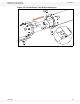
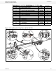
3.2.7. INSTALL THE SPEED REDUCER ON THE BOOT
1. Lift the speed reducer and carefully slide it over the gearbox and lower
flighting shafts and against the face of the boot.
Important: Use the supplied lifting lug on the speed reducer.
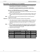
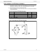
2. Fasten the speed reducer gearbox, PTO shield, and PTO transport strap to
boot using twelve 1/2” x 11-1/2” GR5 bolts and 1/2” locknuts (see Figure 3.13
for details).
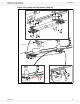
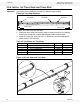
3. Install the lower flight stop as follows ( Figure 3.14):
a. Use a wrench to rotate the lower flight bearing case on the speed reducer
until the bearing case keyway aligns with the lower flight shaft keyway.
b. Insert a 3/8”x3-3/8” square key into the shaft keyway.
c. Slide the lower flight stop over the lower flight shaft, and secure it in place
with a 7/16” x 3-1/2” GR5 bolt and 7/16” locknut.
4. Install the upper gearbox shaft square key as follows ( Figure 3.14):
a. Rotate the upper gearbox shaft bearing case until the bearing case keyway
aligns with the upper gearbox shaft keyway.
b. Insert the 3/8” x 1-3/4” square key into the shaft keyway.
c. Secure the square key with a keyway lock washer, a 3/8” lock washer, and
a 3/8” x 1-1/2” GR5 bolt.
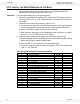
Table 3.8 Install the Speed Reducer on the Boot
Diagram # Description Part # Quantity
1 Speed reducer 20558 1
2 Upper gearbox shaft n/a 1
3 Lower flight gearbox shaft n/a 1
4 PTO driveline strap 20705 1
5 PTO shield n/a 1
6 1/2” x 11-1/2” GR5 bolts 20777 12
7 1/2” locknuts 19599 12
8 Upper gearbox bearing case n/a 1
9 Upper gearbox shaft n/a 1
10 Lower flight bearing case n/a 1
11 Lower flight gearbox shaft n/a 1
12 Lower flight stop 20680 1
13 3/8” x 3-3/8” square key 11910 1
14 7/16” x 3-1/2” GR5 bolt 19547 1
15 7/16” locknut 19598 1
16 3/8” x 1-3/4” square key 17066 1
17 Keyway lock washer 20764 1
18 3/8” lock washer 19604 1
19 3/8” x 1-1/2” GR5 bolt 9900637 1