GRAIN AUGERS X160-85/105/125 ASSEMBLY & OPERATION Read this manual before using product. Failure to follow instructions and safety precautions can result in serious injury, death, or property damage. Keep manual for future reference.
This product has been designed and constructed according to general engineering standardsa. Other local regulations may apply and must be followed by the operator. We strongly recommend that all personnel associated with this equipment be trained in the correct operational and safety procedures required for this product. Periodic reviews of this manual with all employees should be standard practice. For your convenience, we include this sign-off sheet so you can record your periodic reviews.
WHEATHEART GRAIN AUGERS X160-85, X160-105, X160-125 TABLE OF CONTENTS 1. Introduction .......................................................................................................................... 7 1.1. Overview .................................................................................................................. 8 1.1.1. Grain Transfer Boot and PTO Driveline...................................................... 9 1.1.2. Grain Hopper ................................................
WHEATHEART GRAIN AUGERS X160-85, X160-105, X160-125 TABLE OF CONTENTS 3.7. Connect the Auger Tube to the Frame ................................................................... 71 3.8. Install Lift Cylinder Cables to the Track shoe ........................................................ 74 3.9. Connect Hydraulic Hoses and Ball Valve ............................................................... 76 3.10. Connect the PTO Driveline...........................................................................
WHEATHEART GRAIN AUGERS X160-85, X160-105, X160-125 7. Maintenance and Storage................................................................................................ 7.1. Maintenance Intervals .......................................................................................... 7.2. Fluids and Lubricants ........................................................................................... 7.3. Maintenance Procedures .......................................................................
WHEATHEART GRAIN AUGERS X160-85, X160-105, X160-125 6 30875 R0
WHEATHEART - GRAIN AUGERS X160-85, X160-105, X160-125 1. INTRODUCTION 1. Introduction Thank you for purchasing a Wheatheart grain auger. Before using, please read this manual and understand the various features of the equipment and precautions for efficient and safe operation. Keep this manual handy for frequent reference and to review with new personnel. A sign-off form is supplied on the inside front cover to record your safety reviews.
1. INTRODUCTION WHEATHEART - GRAIN AUGERS X160-85, X160-105, X160-125 1.1. OVERVIEW X160 augers are equipped with the following standard features: • • • • • • • a high-capacity grain transfer boot a PTO driveline for auger power.
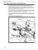
WHEATHEART - GRAIN AUGERS X160-85, X160-105, X160-125 1. INTRODUCTION 1.1.1. GRAIN TRANSFER BOOT AND PTO DRIVELINE The grain transfer boot is located at the bottom of the main auger tube, and contains gearing for power transfer as well as flights for transferring grain. The power source for the auger is a standard 1000 RPM tractor PTO. The PTO driveline connections (both forward and reverse directions) are located on the speed reducer gearbox above the tractor hitch.
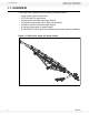
1. INTRODUCTION WHEATHEART - GRAIN AUGERS X160-85, X160-105, X160-125 1.1.2. GRAIN HOPPER The low-profile grain hopper is designed to be rolled into position to receive grain for transfer through the boot to the auger discharge spout. Ground clearance can be adjusted by raising or lowering the position of the hopper wheel axles (see “Connect the Intake Hopper to the Swing Tube” on page 83).
WHEATHEART - GRAIN AUGERS X160-85, X160-105, X160-125 1. INTRODUCTION Figure 1.3 Grain Hopper SPOUT HEAD SWING ARM MAIN AUGER TUBE FLIGHTS AND FLIGHT GUARDING BOOT CLEANOUT HATCH INTAKE HOPPER Figure 1.
1. INTRODUCTION WHEATHEART - GRAIN AUGERS X160-85, X160-105, X160-125 1.1.3. AUGER TUBE HYDRAULIC LIFT The auger tube is raised and lowered using single-acting hydraulic cylinders powered by the hydraulic supply of the connected tractor. The main auger tube is raised by extending the cylinders, and lowered by allowing the cylinders to retract. (see Figure 1.5).
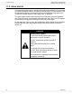
WHEATHEART - GRAIN AUGERS X160-85, X160-105, X160-125 2. SAFETY 2. Safety 2.1. GENERAL SAFETY INFORMATION The Safety Alert symbol identifies important safety messages on the product and in the manual. When you see this symbol, be alert to the possibility of personal injury or death. Follow the instructions in the safety messages. Why is SAFETY important? • Accidents disable and kill. • Accidents cost. • Accidents can be avoided.
2. SAFETY WHEATHEART - GRAIN AUGERS X160-85, X160-105, X160-125 YOU are responsible for the SAFE use and maintenance of your equipment. YOU must ensure that you and anyone else who is going to work around the equipment understands all procedures and related SAFETY information contained in this manual. Remember, YOU are the key to safety. Good safety practices not only protect you, but also the people around you. Makethese practices a working part of your safety program.
WHEATHEART - GRAIN AUGERS X160-85, X160-105, X160-125 2. SAFETY 2.3. OPERATION SAFETY • Have another trained person nearby who can shut down the auger in case of accident. Always work with a second trained person around augers. • Do not operate with any of the safety guards removed. • Keep body, hair, and clothing away from moving parts. Stay away from intake during operation. • Inspect lift cable before using auger. Replace if frayed or damaged.
2. SAFETY WHEATHEART - GRAIN AUGERS X160-85, X160-105, X160-125 Figure 2.
WHEATHEART - GRAIN AUGERS X160-85, X160-105, X160-125 2. SAFETY 2.4. PTO SAFETY • Never use a PTO driveline without a rotating shield in good working order. • Ensure PTO driveline is securely attached at both ends before operating. • Before starting tractor, turn power to PTO to the off position (where applicable). • Keep body, hair, and clothing away from rotating PTO driveline. • Ensure the PTO driveline shields turn freely on the PTO driveline. • Do not exceed PTO operating speed of 1000 rpm.
2. SAFETY WHEATHEART - GRAIN AUGERS X160-85, X160-105, X160-125 2.6. TRANSPORT & PLACEMENT SAFETY • Transport auger in full down position with slight tension on cable. • Properly place hitch pin and securely attach safety chain. Use a type of hitch pin that will not allow auger to separate from towing vehicle. • Always attach an SMV (slow moving vehicle) sign before transporting auger. Equip the auger with the necessary lights for transportation where required by law.
WHEATHEART - GRAIN AUGERS X160-85, X160-105, X160-125 2. SAFETY • Use only genuine Wheatheart replacement parts or equivalent. Replacement parts such as intake guards, pulley guards, PTO driveline shields, winches, and lift cables must meet ASABE standards or serious injury may result. Use of unauthorized parts will void warranty. If in doubt, contact Wheatheart or your Wheatheart dealer. • Do not modify any auger components without authorization from Wheatheart.
2. SAFETY WHEATHEART - GRAIN AUGERS X160-85, X160-105, X160-125 Table 2.1. Safety Decal Description, Detail, and Location Information Number Description 20806 High pressure fluid hazard (Warning) 20809 Rotating cable sheaves hazard (Warning) Detail Figure 2.7 Figure 2.8 21074 Auger-to-tractor hookup (Notice) Figure 2.9 18859 17378 Disconnect PTO driveline (Notice) Transport restrictions (Notice) Figure 2.10 Figure 2.11 20816 Electrocution hazard (Danger) Figure 2.
WHEATHEART - GRAIN AUGERS X160-85, X160-105, X160-125 2. SAFETY Figure 2.2 Hydraulic Safety Decal Locations DECAL #20806 WARNING HIGH PRESSURE FLUID HAZARD Hydraulic fluid can cause serious injury if it penetrates the skin. If it does, see a doctor immediately. • Relieve pressure before unhooking hydraulic line. • Wear proper hand and eye protection, and use wood or cardboard, not hands, when searching for leaks.
2. SAFETY WHEATHEART - GRAIN AUGERS X160-85, X160-105, X160-125 Figure 2.3 PTO and Towbar Safety Decal Locations DECAL #21074 NOTICE DECAL #18859 To prevent damage during auger-totractor hookup: • Follow dimensions above for correct auger-to-tractor hookup. • Auger must be on level ground and in full down position when measuring. • Adjust drawbar as needed. • See operation manual for complete details.
WHEATHEART - GRAIN AUGERS X160-85, X160-105, X160-125 2. SAFETY Figure 2.4 Auger Tube and Hopper Safety Decal Locations DECAL #20806 DECAL # 28616 WARNING HIGH PRESSURE FLUID HAZARD Hydraulic fluid can cause serious injury if it penetrates the skin. If it does, see a doctor immediately. DECAL #20813 • Relieve pressure before unhooking hydraulic line. • Wear proper hand and eye protection, and use wood or cardboard, not hands, when searching for leaks.
2. SAFETY WHEATHEART - GRAIN AUGERS X160-85, X160-105, X160-125 Figure 2.5 Boot Safety Decal Locations DECAL #20807 WARNING DECAL #20813 DECAL #20816 DANGER DANGER To prevent serious injury or death: • Read and understand the manual before assembling, operating, or maintaining the equipment. • Only trained personnel may assemble, operate, or maintain the equipment.
WHEATHEART - GRAIN AUGERS X160-85, X160-105, X160-125 2. SAFETY Figure 2.6 Lower Frame Safety Decal Location NOTE: TWO DECALS ARE REQUIRED, ONE ON EACH SIDE OF THE AXLE WARNING ROLLOVER / TRANSPORT HAZARD To prevent serious injury or death: • Fully extend axles before raising auger tube. • Retract axles before transporting.
2. SAFETY WHEATHEART - GRAIN AUGERS X160-85, X160-105, X160-125 2.8.3. SAFETY DECAL DETAIL WARNING HIGH PRESSURE FLUID HAZARD Hydraulic fluid can cause serious injury if it penetrates the skin. If it does, see a doctor immediately. • Relieve pressure before unhooking hydraulic line. • Wear proper hand and eye protection, and use wood or cardboard, not hands, when searching for leaks. Made in Canada 20806 Figure 2.
WHEATHEART - GRAIN AUGERS X160-85, X160-105, X160-125 2. SAFETY NOTICE To prevent damage during auger-totractor hookup: • Follow dimensions above for correct auger-to-tractor hookup. • Auger must be on level ground and in full down position when measuring. • Adjust drawbar as needed. • See operation manual for complete details. 21074 Made in Canada Figure 2.9 Decal 21074 NOTICE Disconnect PTO driveline from tractor before moving equipment.
2. SAFETY WHEATHEART - GRAIN AUGERS X160-85, X160-105, X160-125 NOTICE This equipment is not intended for transport on public roads. If it must be moved, check local regulations. To avoid damaging the equipment: • Be careful when turning corners. • Watch for low overhead objects. • Retract axles before transporting unit. 17378 Made in Canada Figure 2.
WHEATHEART - GRAIN AUGERS X160-85, X160-105, X160-125 2. SAFETY DANGER ROTATING FLIGHTING HAZARD To prevent death or serious injury: • KEEP AWAY from rotating auger flighting. • DO NOT remove or modify auger flighting guards, doors, or covers. Keep in good working order. Have replaced if damaged. 20813 Made in Canada • DO NOT operate the auger without all guards, doors, and covers in place. • NEVER touch the auger flighting. Use a stick or other tool to remove an obstruction or clean out.
2. SAFETY WHEATHEART - GRAIN AUGERS X160-85, X160-105, X160-125 WARNING To prevent serious injury or death: • Read and understand the manual before assembling, operating, or maintaining the equipment. • Only trained personnel may assemble, operate, or maintain the equipment. • Children and untrained personnel must be kept outside of the work area. • If the manual, guards, or decals are missing or damaged, contact factory or dealer for replacements. • Lock out power before performing maintenance.
WHEATHEART - GRAIN AUGERS X160-85, X160-105, X160-125 2. SAFETY WARNING UPENDING HAZARD To prevent death or serious injury: • Anchor intake end and/or support discharge end to prevent upending. • Do not raise auger intake end above tow bar height. • Auger intake end must always have downward weight. Do not release until attached to tow bar or resting on ground. • Empty auger and fully lower before moving. 20811 Made in Canada Figure 2.
2. SAFETY WHEATHEART - GRAIN AUGERS X160-85, X160-105, X160-125 WARNING ENTANGLEMENT HAZARD To prevent serious injury or death: • Keep body, hair, and clothing away from rotating pulleys, belts, chains, and sprockets. • Do not operate with any guard removed or modified. Keep guards in good working order. • Shut off and remove key or lock out power before source before inspecting or servicing machine. 20804 Made in Canada (LOCATED ON HOPPER CHAIN GUARD) Figure 2.
WHEATHEART - GRAIN AUGERS X160-85, X160-105, X160-125 2. SAFETY DANGER ROTATING FLIGHTING INSIDE To prevent serious injury or death, do not operate auger unless swinghopper is securely attached to boot. Made in Canada 17094 Figure 2.19 Decal 17094 NOTICE To prevent damage, wheels must be free to move when raising or lowering equipment. When equipment is positioned, chock Made in Canada 19960 all wheels. Figure 2.
2. SAFETY WHEATHEART - GRAIN AUGERS X160-85, X160-105, X160-125 WARNING MISSING GUARD HAZARD To prevent serious injury or death, shut off power and reattach guard before operating machine. Made in Canada 20803 PLACED ON MACHINE BEHIND GUARD Figure 2.22 Decal 20803 WARNING ROLLOVER / TRANSPORT HAZARD To prevent serious injury or death: • Fully extend axles before raising auger tube. • Retract axles before transporting. 20812 Made in Canada Figure 2.
WHEATHEART - GRAIN AUGERS X160-85, X160-105, X160-125 3. ASSEMBLY 3. Assembly WARNING Before continuing, ensure you have read and understand the relevant information in the safety section. Safety information is provided to help prevent serious injury, death, or property damage. Before beginning assembly, familiarize yourself with all the sub-assemblies and hardware making up the auger. Have all parts on hand and arrange them for easy access. Carry out assembly in a large open area with a level surface.
3. ASSEMBLY WHEATHEART - GRAIN AUGERS X160-85, X160-105, X160-125 • • • • 1/2” drive impact wrench (recommended) 1/2” extension 3/8”, 5/8”, 3/4”, and 15/16” sockets for 1/2” drive 3/8”, 5/8”, 3/4” and 15/16” flat wrenches See Table 3.1. for a list of assembly procedures. Table 3.1.
WHEATHEART - GRAIN AUGERS X160-85, X160-105, X160-125 3. ASSEMBLY 3.2. ASSEMBLE THE AUGER TUBE 3.2.1. IDENTIFY AND ARRANGE AUGER TUBE SECTIONS Important: 1. Align tube sections on a series of support stands, placing a support stand at the end of each tube (see Figure 3.1 through Figure 3.3 for correct tube positioning, according to auger model). 2. As tubes sections are added, make sure that support stands are at equal heights across all tubes to ensure that tubes are level with each other.
3. ASSEMBLY WHEATHEART - GRAIN AUGERS X160-85, X160-105, X160-125 Figure 3.
WHEATHEART - GRAIN AUGERS X160-85, X160-105, X160-125 3. ASSEMBLY Figure 3.
3. ASSEMBLY WHEATHEART - GRAIN AUGERS X160-85, X160-105, X160-125 3.2.2. CONNECT AUGER TUBES Important: Always strap tubes to the support stands to prevent the tubes from rolling off the stands. Note: Assemble the auger tube starting with the discharge section and working toward the intake section. 1. Bolt tube sections together (see Figure 3.5 for details), working from the spout end (upper tube) toward the discharge end (lower tube): a.
WHEATHEART - GRAIN AUGERS X160-85, X160-105, X160-125 3. ASSEMBLY Figure 3.
3. ASSEMBLY WHEATHEART - GRAIN AUGERS X160-85, X160-105, X160-125 3.2.3. INSTALL THE HYDRAULIC LIFT CYLINDERS • See “Install the X160-85 Hydraulic Lift Cylinders” below for information on installing hydraulic lift cylinders on X160-85 augers. • See “Install the X160-105/125 Hydraulic Lift Cylinders” on page 44 for information on installing hydraulic lift cylinders on X160-105/125 augers. INSTALL THE X160-85 HYDRAULIC LIFT CYLINDERS Note: Important: Note: 1.
WHEATHEART - GRAIN AUGERS X160-85, X160-105, X160-125 3. ASSEMBLY Figure 3.
3. ASSEMBLY WHEATHEART - GRAIN AUGERS X160-85, X160-105, X160-125 INSTALL THE X160-105/125 HYDRAULIC LIFT CYLINDERS 1. Identify the tube section where the hydraulic lift cylinders install, and note the location of the tube cylinder mounts. 2. Ensure that the tube cylinder mounts are facing down. 3. Fasten two rear cylinder attach brackets to the rear cylinder mounts with eight 5/8” x 2” GR8 bolts and locknuts. 4.
WHEATHEART - GRAIN AUGERS X160-85, X160-105, X160-125 3. ASSEMBLY Table 3.
3. ASSEMBLY WHEATHEART - GRAIN AUGERS X160-85, X160-105, X160-125 3.2.4. INSTALL THE TRACK SHOE AND TRACK STOP Important: See Figure 3.9 for track stop positions for specific auger models. Figure 3.9 Track Stop Positions 125’ MODEL 85’ MODEL 105’ MODEL INTAKE END SPOUT END 1. Slide the track shoe onto the track. 2. Slide track shoe along full length of track to make sure there is no binding, and that track ends are properly aligned where tube sections meet. 3.
WHEATHEART - GRAIN AUGERS X160-85, X160-105, X160-125 3. ASSEMBLY 3.2.5. INSTALL THE BOOT ON THE AUGER TUBE .\ WARNING Components are heavy and create a crushing hazard if improperly handled. Be sure to use proper hoisting equipment and procedures, and ensure lifting apparatus is secure. Lock out the lifting apparatus before working around or under the raised components; failure to do so may cause serious personal injury. Note: The gearbox is sent from the factory filled half way with gear oil.
3. ASSEMBLY WHEATHEART - GRAIN AUGERS X160-85, X160-105, X160-125 Figure 3.
WHEATHEART - GRAIN AUGERS X160-85, X160-105, X160-125 3. ASSEMBLY 3.2.6. ASSEMBLE THE PTO SHIELD ASSEMBLY 1. As shown in Figure 3.12, align the PTO shield front on the PTO shield rear and secure it with three 5/16” x 3/4” bolts [19538] and 5/16” whiz nuts. 2. Insert the hair pin to lock PTO shield with base. 3. Set the assembled PTO shield assembly aside for use during the installation of the speed reducer. Table 3.
3. ASSEMBLY WHEATHEART - GRAIN AUGERS X160-85, X160-105, X160-125 3.2.7. INSTALL THE SPEED REDUCER ON THE BOOT Important: 1. Lift the speed reducer and carefully slide it over the gearbox and lower flighting shafts and against the face of the boot. Use the supplied lifting lug on the speed reducer. 2. Fasten the speed reducer gearbox, PTO shield, and PTO transport strap to boot using twelve 1/2” x 11-1/2” GR5 bolts and 1/2” locknuts (see Figure 3.13 for details). 3.
WHEATHEART - GRAIN AUGERS X160-85, X160-105, X160-125 3. ASSEMBLY Figure 3.
3. ASSEMBLY WHEATHEART - GRAIN AUGERS X160-85, X160-105, X160-125 Figure 3.
WHEATHEART - GRAIN AUGERS X160-85, X160-105, X160-125 3. ASSEMBLY 3.2.8. INSTALL THE BOOT TOW BAR 1. Insert the tow bar into the boot channel (see Figure 3.15), and secure the back end loosely with a 3/4” x 6-1/2” bolt and 3/4” locknut through the hole in the boot channel. 2. Tightly secure the middle of the tow bar in channel with a 3/4” x 4-1/16” x 5-3/4” U-bolt and two 3/4” locknuts. 3. Fully tighten the 3/4” nut on the 3/4” x 6-1/2” bolt. Table 3.
3. ASSEMBLY WHEATHEART - GRAIN AUGERS X160-85, X160-105, X160-125 3.2.9. INSTALL THE DISCHARGE SPOUT DISCHARGE SPOUT 1. Align the discharge spout over the opening in the upper tube. 2. Attach the discharge spout with two 5/8” x 3” GR5 bolts [17745] and 5/8” locknuts [19600] on each side. Table 3.10 Install the Boot Tow Bar Diagram # 1 2 3 4 Description Discharge spout Opening in upper tube 5/8” x 3” GR5 bolts 5/8” locknuts Part # 53090 n/a 17745 19600 Quantity 1 1 1 1 Figure 3.
WHEATHEART - GRAIN AUGERS X160-85, X160-105, X160-125 3. ASSEMBLY 3.2.10. SET THE THRUST ADJUSTER 1. Remove the upper bearing lock collar (if necessary). 2. Slide the lock collar and bushing onto the shaft and attach the 1-1/2” nut. 3. Turn the nut until boot flight stop snug against the speed reducer gearbox, then keep turning it until all tube flights are turning with the shaft. 4. Secure the lock collar and tighten the set screw. 5. Install the cover over the two longer 5/8” bolts.
3. ASSEMBLY WHEATHEART - GRAIN AUGERS X160-85, X160-105, X160-125 3.2.11. APPLY LOGO AND MODEL DECALS ON THE AUGER TUBES 1. Prepare surface by cleaning thoroughly with soap and water. Surface must be clean and free of dirt, grime, rust and oil. To clean oily surface, wipe with clean cloth and solvent cleaner or isopropyl alcohol. 2. Position the decal on the tube and apply masking tape along the top, creating a gate hinge. Figure A demonstrates. 3.
WHEATHEART - GRAIN AUGERS X160-85, X160-105, X160-125 3. ASSEMBLY AUGER MODEL LOWER MIDDLE TUBE (DISCHARGE SIDE) UPPER TUBE WESTFIELD LOGO, CENTRED ON SIDE OF UPPER TUBE Figure 3.
3. ASSEMBLY WHEATHEART - GRAIN AUGERS X160-85, X160-105, X160-125 3.3. INSTALL TRUSS SUPPORT TOWERS AND TRUSS TUBES Note: Due to rigidity of the tubular trussing, do not put an upward bow in the auger. Assemble trussing with main auger tube straight/level and well supported over its length. When assembling the truss system, DO NOT tighten any bolts until all components are in place. • See Figure 3.19 and Figure 3.22 for the X160-85. • See Figure 3.20 and Figure 3.23 for the X160-105. • See Figure 3.
WHEATHEART - GRAIN AUGERS X160-85, X160-105, X160-125 3. ASSEMBLY 9. Rotate the loose “inner” 1” hex nuts on the truss adjust tubes toward the “outer” nut until they are locked tightly against their respective truss anchor brackets. Table 3.11.
3. ASSEMBLY WHEATHEART - GRAIN AUGERS X160-85, X160-105, X160-125 LOW 2 HIGH HIGH HIGH HIGH LOW 2 2 Figure 3.
WHEATHEART - GRAIN AUGERS X160-85, X160-105, X160-125 3. ASSEMBLY LOW 2 HIGH HIGH HIGH HIGH HIGH HIGH 2 LOW 2 Figure 3.
3. ASSEMBLY WHEATHEART - GRAIN AUGERS X160-85, X160-105, X160-125 LOW HIGH 2 HIGH HIGH HIGH HIGH HIGH HIGH HIGH LOW 2 2 Figure 3.
3. ASSEMBLY 14 16 4 4 5 5 10 13 6 5 12 8 6 11 16 8 8 1 1 8 13 7 13 8 11 8 10 9 11 7 11 8 11 9 8 11 14 5 15 WHEATHEART - GRAIN AUGERS X160-85, X160-105, X160-125 Figure 3.
WHEATHEART - GRAIN AUGERS X160-85, X160-105, X160-125 16 12 8 5 4 4 5 10 13 6 5 8 6 11 16 8 8 1 1 8 13 7 13 8 8 11 10 9 11 8 7 11 11 14 8 9 8 11 14 5 15 3. ASSEMBLY Figure 3.
3. ASSEMBLY 8 11 8 12 8 5 4 5 4 10 13 6 5 8 6 16 8 8 1 1 8 13 7 8 13 11 8 16 10 9 11 7 11 11 8 9 14 8 8 11 14 5 15 WHEATHEART - GRAIN AUGERS X160-85, X160-105, X160-125 Figure 3.
3. ASSEMBLY WHEATHEART - GRAIN AUGERS X160-85, X160-105, X160-125 3.4. INSTALL TRUSS CABLES See Figure 3.25 for details (X160-85 shown, other models are similar). 1. Attach eyebolts (1) to both ends of a truss cable (3) with two 1/2” cable clamps (2), using about 10” (25.4 cm) to 12” (30.5 cm) of cable. Tighten securely. 2. Thread the cable through the cable return bracket (4) on the underside of the lower tube, and pull the cable through until there is an equal length of cable on each side of the tube.
3. ASSEMBLY 3 2 2 2 1 5 6 4 1 2 2 2 1 3 3 8 7 5 3 5 WHEATHEART - GRAIN AUGERS X160-85, X160-105, X160-125 Figure 3.
3. ASSEMBLY WHEATHEART - GRAIN AUGERS X160-85, X160-105, X160-125 3.5. ASSEMBLE THE LOWER FRAME 1. Fasten the lower reach arms to the axle with four 3/4” x 2” bolts and locknuts on each side. Tighten securely. 2. Attach the short cross member between the lower reach arms with four 1/2” x 1-1/2” bolts and locknuts on each side. Tighten securely. Figure 3.26 Assembling the Lower Frame 6 13 (X4) 10 (X4) 6 5 11 1 4 12 7 4 13 5 9 8 7 2 4 15 11 12 4 14 4 13 4 14 3.
WHEATHEART - GRAIN AUGERS X160-85, X160-105, X160-125 3. ASSEMBLY 4. Secure the frame cross braces and the long frame cross brace to the welded lugs on the lower reach arms with four 1/2” x 1-3/4” bolts, 1/2” flat washers, and locknuts. Use a fifth 1/2” x 1-1/2” bolt, 1/2” flat washer, and locknut to fasten the cross-braces together where they cross. Table 3.13.
3. ASSEMBLY WHEATHEART - GRAIN AUGERS X160-85, X160-105, X160-125 3.6. ASSEMBLE THE WHEEL HUB AND INSTALL TIRES 1. Remove any dirt or paint from spindle and hub. 2. Thoroughly pack wheel bearings and cups with a high-quality SAE approved extreme pressure rated bearing grease. 3. Place large bearing into hub and carefully tap in seal. 4. Slip hub onto spindle and insert small bearing and washer. 5. T ighten slotted spindle nut until hub drags slightly.
WHEATHEART - GRAIN AUGERS X160-85, X160-105, X160-125 3. ASSEMBLY 3.7. CONNECT THE AUGER TUBE TO THE FRAME 1. Raise the discharge end of auger (e.g. with a front end loader and a strong sling or with a chain or block and tackle). The height should be sufficient to clear the undercarriage assembly. WARNING Do not remove tube support until the assembly in this section has been completed. 2. Place undercarriage beneath tube assembly. 3. Connect the lower lift arms to the auger tube: a.
3. ASSEMBLY WHEATHEART - GRAIN AUGERS X160-85, X160-105, X160-125 9. Lower upper end of auger slowly until track shoe rests against upper track stop and the lift assist stops rest against track. 10. For X160-105/125, attach a short cross-member between the upper lift arms using eight 1/2” x 1-1/2” bolts and 1/2” locknuts. Tighten securely. Table 3.
WHEATHEART - GRAIN AUGERS X160-85, X160-105, X160-125 3. ASSEMBLY 3 18 9 1 1 30875 R0 8 3 4 9 1 19 7 5 10 6 3 4 8 7 22 20 2 14 20 6 8 9 21 14 14 4 13 2 13 17 13 3 16 17 19 4 15 15 Figure 3.
3. ASSEMBLY WHEATHEART - GRAIN AUGERS X160-85, X160-105, X160-125 3.8. INSTALL LIFT CYLINDER CABLES TO THE TRACK SHOE CAUTION Track shoe must rest against track stop when adjusting cable. If this isn’t done, the auger can raise higher than designed to lift, resulting in damage to auger and possible injury to personnel.
WHEATHEART - GRAIN AUGERS X160-85, X160-105, X160-125 Important: 3. ASSEMBLY The X160-85 model requires four 5/16” cable clamps (19333) per cable, and the X160-105/125 models require four 1/2” cable clamps (20606) per cable. WARNING Ensure that cable clamps are positioned with the U-bolt portion of the clamp on the unloaded side of the lift cables (see Figure 3.29).
3. ASSEMBLY WHEATHEART - GRAIN AUGERS X160-85, X160-105, X160-125 3.9. CONNECT HYDRAULIC HOSES AND BALL VALVE Note: Elbow fittings are factory installed. Use thread sealant on fitting and hose threads (not supplied.) Table 3.
WHEATHEART - GRAIN AUGERS X160-85, X160-105, X160-125 Important: 3. ASSEMBLY a. For X160-85 models, route the hoses across the backarm bracket to the opposite side of the auger tube, then to the hydraulic hose catch on side of auger tube. b. For X160-105/125 models, route the hoses to the hydraulic hose catch on side of the auger tube. 7. Tighten hydraulic hose catch snugly enough to hold hoses in place (see Figure 3.34). 8.
3. ASSEMBLY WHEATHEART - GRAIN AUGERS X160-85, X160-105, X160-125 Figure 3.
30875 R0 &\OLQGHU &\OLQGHU &\OLQGHU $ $ &$3 (1' (/%2: ),77,1* > @ 7(( ),77,1* > @ 6+257 +<'5$8/,& +26( > @ $ 6+257 +<'5$8/,& +26( > @ /21* +<'5$8/,& /,)7 +26( 35(6685( :,7+ %$// 9$/9( $1' 3,21((5 &283/(5 /21* +<'5$8/,& /,)7 +26( )/8,' 5(7851 :,7+ 3,21((5 &283/(5 52' (1' %$// 9$/9( 21 %227 WHEATHEART - GRAIN AUGERS X160-85, X160-105, X160-125 3. ASSEMBLY Figure 3.
80 &\OLQGHU &\OLQGHU $ (/%2: ),77,1* > @ 7(( ),77,1* > @ 6+257 +<'5$8/,& +26( > @ $ 6+257 +<'5$8/,& +26( > @ /21* +<'5$8/,& /,)7 +26( 35(6685( :,7+ %$// 9$/9( $1' 3,21((5 &283/(5 /21* +<'5$8/,& /,)7 +26( )/8,' 5(7851 :,7+ 3,21((5 &283/(5 %$// 9$/9( 21 %227 3. ASSEMBLY WHEATHEART - GRAIN AUGERS X160-85, X160-105, X160-125 Figure 3.
WHEATHEART - GRAIN AUGERS X160-85, X160-105, X160-125 3. ASSEMBLY Figure 3.34 Installing Hose Clips 5/16” LOCKNUT (1980) 5/16” X1-1/4” BOLT (17748) HYDRAULIC HOSE CLIP (20607) Figure 3.
3. ASSEMBLY WHEATHEART - GRAIN AUGERS X160-85, X160-105, X160-125 3.10. CONNECT THE PTO DRIVELINE 1. Clean dirt off of stub shaft (20605) ends before assembly. 2. Install the stub shaft on the PTO driveline using a 3/8” x 1-3/4” square key (17066) and a 3/8” x 2-1/2” coil roll pin (18546). Tighten the 3/8” x 3/8” set screw on the PTO driveline. Figure 3.36 Connecting the Stub Shaft to the PTO Driveline 3. Insert the splined end of the PTO stub shaft into the “forward” speed reducer gear box position. 4.
WHEATHEART - GRAIN AUGERS X160-85, X160-105, X160-125 3. ASSEMBLY 3.11. CONNECT THE INTAKE HOPPER TO THE SWING TUBE WARNING Components are heavy andcreate a crushing hazard if improperly handled. Be sure to use proper hoisting equipment and procedures, and ensure lifting apparatus is secure. Lockout the lifting apparatus before working around or under the raised components. Failure to do so may cause serious personal injury. Table 3.16.
3. ASSEMBLY WHEATHEART - GRAIN AUGERS X160-85, X160-105, X160-125 1. Secure the transition to the swing tubewith twelve 5/8” x 1-1/2” bolts and 5/8” locknuts. Figure 3.38 Installing the Transition to the Swing Tube 3 4 2 1 2. Thoroughly grease two 1-3/4” flat washers, then place them fully onto the end of the swing flight shaft. 3. Place the bushing support onto the swing flight shaft and secure it in place with two 3/8” x 1” bolts, 3/8” flat washers, and locknuts. 4.
WHEATHEART - GRAIN AUGERS X160-85, X160-105, X160-125 3. ASSEMBLY Figure 3.39 Secure Bushing Support and Connect Transition Flight 12 13 15 6 11 5 7 8 14 9 16 10 7. Raise and support the hopper tube spout head on a stand about 50” high. 8. Open the service door on the transition, then bring the intake hopper and transition together guiding the transition flight shaft into the u-joint (Figure 3.40). 9. Attach the transition to the intake hopper with two 5/8” x 2” bolts and 5/8” locknuts.
3. ASSEMBLY WHEATHEART - GRAIN AUGERS X160-85, X160-105, X160-125 Figure 3.40 Connecting the Transition to the Intake Hopper 18,19 18,19 7 10. Attach the 6 solid wheels to the 4 hopper corners with the axle pins and hairpins. There are 3 height settings (Figure 3.41) that can be used according to preference. Figure 3.
WHEATHEART - GRAIN AUGERS X160-85, X160-105, X160-125 3. ASSEMBLY 3.12. CONNECT THE SPOUT HEAD TO THE GRAIN TRANSFER BOOT Table 3.17.
3. ASSEMBLY WHEATHEART - GRAIN AUGERS X160-85, X160-105, X160-125 Figure 3.
WHEATHEART - GRAIN AUGERS X160-85, X160-105, X160-125 3. ASSEMBLY 3.13. INSTALL THE HOPPER LIFT ARM Note: 1. Determine which side of the auger the hopper will be operating on. Feed side of hopper must face the main auger when in transport. 2. Position the hopper lift arm assembly on the mount bracket on top of the lower auger tube with the arm overhanging the side of the auger that the hopper will be operating on. 3.
3. ASSEMBLY WHEATHEART - GRAIN AUGERS X160-85, X160-105, X160-125 3.14. INSTALL THE HYDRAULIC WINCH 1. Position the hydraulic winch on the winch mounting plate, and secure it using three 3/8” washers and three 3/8” locknuts as shown in Figure 3.44. 2.
WHEATHEART - GRAIN AUGERS X160-85, X160-105, X160-125 3. ASSEMBLY Figure 3.
3. ASSEMBLY WHEATHEART - GRAIN AUGERS X160-85, X160-105, X160-125 Figure 3.46 Installing the Hydraulic Winch Hose B B C C PART 92 DESCRIPTION A STEEL ELBOW 90.
WHEATHEART - GRAIN AUGERS X160-85, X160-105, X160-125 3. ASSEMBLY 3.15. POWER SWING ASSEMBLY TRANSMITTER WHEEL AND TIRE ASSEMBLY RECEIVER CLAMP ASSEMBLY LOWER CLAMP ASSEMBLY POWER SWING ASSEMBLY Figure 3.47 Electric Power Swing Components Table 3.
3. ASSEMBLY WHEATHEART - GRAIN AUGERS X160-85, X160-105, X160-125 3.15.1. CONNECT THE LOWER CLAMP TO THE POWER SWING 1. Position the lower clamp assembly onto the power swing assembly. As shown in Figure 3.48, the long side of the lower clamp must face away from the wheels. 2. Fasten the lower clamp assembly to the power swing assembly: a. For the front of the clamp, use two 5/8” x 1-1/2” bolts and locknuts for the pivot point (at the front of the clamp). b.
WHEATHEART - GRAIN AUGERS X160-85, X160-105, X160-125 3. ASSEMBLY 3.15.3. CONNECT THE POWER SWING WHEEL ASSEMBLY TO THE TUBE 1. Position the power swing underneath the swing tube. Position the power swing axle so that the bottom clamp is on the same inclination as the swing tube (see Figure 3.50 for clarification). Move the power swing down the swing tube as far as possible (as close to the intake hopper as possible). 2.
3. ASSEMBLY WHEATHEART - GRAIN AUGERS X160-85, X160-105, X160-125 3.15.4. CONNECTING THE POWER SWING WIRING 1. Remove cover from the receiver box and top clamp assembly. This means removing the four sheet metal screws (#14 x 5/8”) located on the sides of the cover. See Figure 3.50. 2. Remove radio antenna and transmitter from the crate (it will be in a separate bag). Screw antenna into the socket on the clamp-base. 3.
WHEATHEART - GRAIN AUGERS X160-85, X160-105, X160-125 3. ASSEMBLY Figure 3.51 Receiver Box RECEIVER BOX LONG CABLE SHORT CABLE 4. The electrical cables are pre-installed to the receiver box. Uncoil the shorter, 4’ electrical cable and identify the positive and negative wires by referring to Figures 3.52 and 3.53. The positive wire has a red boot and printing on it. 5. Attach the wires to the motor terminals on the Power Swing as shown in Figures 3.52 and 3.53.
3. ASSEMBLY WHEATHEART - GRAIN AUGERS X160-85, X160-105, X160-125 Figure 3.52 Electric Motor Wiring ELECTRIC MOTOR NEGATIVE WIRE CONNECTS TO NEGATIVE MOTOR TERMINAL. LONG ELECTRICAL CABLE CONNECTS TO TRACTOR CHASSIS AND BATTERY. POSITIVE WIRE WITH RED BOOT CONNECTS TO POSITIVE MOTOR TERMINAL. SHORT ELECTRICAL CABLE CONNECTS TO ELECTRIC MOTOR ON POWER SWING. NEGATIVE WIRE CONNECTS TO TRACTOR CHASSIS. POSITIVE WIRE WITH CIRCUIT BREAKER CONNECTS TO POSITIVE BATTERY TERMINAL. 6.
WHEATHEART - GRAIN AUGERS X160-85, X160-105, X160-125 3. ASSEMBLY Figure 3.
3. ASSEMBLY WHEATHEART - GRAIN AUGERS X160-85, X160-105, X160-125 3.17. INSTALL THE MANUAL CONTAINER Before beginning installation, ensure that all winch / auger lift controls are locked in place and shut down and/or lock out auger. 1. Remove the transparent window from the side of the boot. 2.
WHEATHEART - GRAIN AUGERS X160-85, X160-105, X160-125 3. ASSEMBLY 3.18. AUGER-TO-TRACTOR HOOKUP Important: The X160 auger must be correctly connected to the tractor for all operations, including transport, raising, placement, and when augering grain. The final stage of the assembly is attaching the auger to the tractor. When attaching the auger to your tractor, the only suitable hitch is a clevis-type hitch that is appropriately sized and rated for towing the auger.
3. ASSEMBLY WHEATHEART - GRAIN AUGERS X160-85, X160-105, X160-125 Figure 3.56 Measurements Between Drawbar and PTO Driveline A………………………………14” (35.6 cm) B………………………………10”- 14” (25.4 cm - 35.6 cm) C………………………………46” (116.8 cm) (MUST BE TAKEN WITH AUGER ON LEVEL GROUND AND IN FULL DOWN POSITION) RAISE TRACTOR DRAWBAR IF NECESSARY TO MAINTAIN (B) DIMENSION OF 10” - 14” (25.4 cm - 35.6 cm) C A B MEASUREMENT If (A) is less than 14” (35.6 cm) (C) will be less than the recommended 46” (116.
WHEATHEART - GRAIN AUGERS X160-85, X160-105, X160-125 4. TRANSPORT 4. Transport WARNING Before continuing, ensure you have read and understand the relevant information in the safety section. Safety information is provided to help prevent serious injury, death, or property damage. This auger is designed to be transported and operated without unhitching unit from tractor. CAUTION Always tow auger in the lowered position. Disconnect PTO driveline from tractor for transport and placement.
4. TRANSPORT WHEATHEART - GRAIN AUGERS X160-85, X160-105, X160-125 8. Place swivel jack (on side of hitch) in transport position and lock. Figure 4.1 Retract Wheel Axles JACK LUG AXLE AXLE PIN Figure 4.
WHEATHEART - GRAIN AUGERS X160-85, X160-105, X160-125 4. TRANSPORT Figure 4.3 Hopper in Transport Position SAFETY CHAIN AND HOOK WINCH CHAIN AND HOOK CAUTION If auger wheels are partially or fully buried in snow or grain, failure to clear the area around the wheels before moving may cause damage to the auger or result in serious injury. Important: Intake feed side of hopper must face main auger when in transport (Figure 4.3) 9. Clear all untrained personnel from transport zone.
4.
WHEATHEART - GRAIN AUGERS X160-85, X160-105, X160-125 5. PLACEMENT 5. Placement WARNING Before continuing, ensure you have read and understand the relevant information in the safety section. Safety information is provided to help prevent serious injury, death, or property damage. This auger is designed to be transported and operated without unhitching unit from tractor. CAUTION Always tow auger in the lowered position. Disconnect PTO driveline from tractor for transport and placement. 5.1.
5. PLACEMENT WHEATHEART - GRAIN AUGERS X160-85, X160-105, X160-125 5. Connect hydraulic hoses, ensure connections are tight. Check for leaks, binding, flattening, kinks, or wear. NOTICE Replacement hose and hose ends must have a minimum strength of 2500 psi (17200 kPa) working pressure. 6. Extend the wheel axles: a. Ensure that the auger is on level ground before attempting to extend or retract the axle extensions. Auger must be attached to tractor at all times. b.
WHEATHEART - GRAIN AUGERS X160-85, X160-105, X160-125 5. PLACEMENT d. Remove the axle pin from the axle and slide the axle outwards until the second set of holes line up (Figure 5.2). Reinsert the axle pin and secure with snap pin. Lower the jack. Figure 5.2 Extend Axle and Insert Axle Pin JACK LUG EXTEND AXLE INSERT AXLE PIN e. Repeat the process on the other side of the axle to extend the other side. 7.
5. PLACEMENT WHEATHEART - GRAIN AUGERS X160-85, X160-105, X160-125 c. Close hose valve (after auger is positioned). WARNING Do not raise the auger unless the axles are in the extended position. Do not transport the auger unless the axles are in the retracted position. . NOTICE The hydraulic cylinders are shipped without oil and must be charged with oil before auger is put into operation. See the appendix for charging instructions.
WHEATHEART - GRAIN AUGERS X160-85, X160-105, X160-125 5. PLACEMENT Figure 5.
5.
WHEATHEART - GRAIN AUGERS X160-85, X160-105, X160-125 6. OPERATION 6. Operation WARNING Before continuing, ensure you have read and understand the relevant information in the safety section. Safety information is provided to help prevent serious injury, death, or property damage. 6.1. OPERATOR CONTROLS The operator controls the following auger actions during operation: Table 6.
6. OPERATION WHEATHEART - GRAIN AUGERS X160-85, X160-105, X160-125 Figure 6.1 Main Auger Tube Hydraulic Shut-off Valve Figure 6.2 Power Swing Manual Controls Figure 6.
WHEATHEART - GRAIN AUGERS X160-85, X160-105, X160-125 6. OPERATION 6.2. PRE-OPERATION 6.2.1. CHECKLIST • • • • • • • • • • • • • • • • • • • 30875 R0 Tighten all fasteners. Adjust and/or lubricate boot chain and hopper chain. Ensure auger rotates freely. Check that tire pressure is within the manufacturer’s specification. Ensure wheel bolt torque is within specification. Check hopper winch and lift cables for damage (fraying, kinking, unraveling). Replace as required.
6. OPERATION WHEATHEART - GRAIN AUGERS X160-85, X160-105, X160-125 6.2.2. PTO DRIVE Correct operation of the auger requires pre-inspection of the drive system, operator knowledge on how to shut down the system, and a general monitoring of the system during operation. NOTICE When positioning the auger, the PTO driveline must be disconnected from the tractor and placed in the transport saddle to prevent damage to auger and PTO driveline.
WHEATHEART - GRAIN AUGERS X160-85, X160-105, X160-125 6. OPERATION 6.2.4. ELECTRIC POWER SWING OPERATION Remotes will be programmed from the factory—to reprogram your remote (or to add additional remotes, please see the Appendix. Important: Registering more than one remote transmitter to a single Power Swing is acceptable but registering one remote transmitter to multiple Power Swings is not recommended. 1.
6. OPERATION WHEATHEART - GRAIN AUGERS X160-85, X160-105, X160-125 Figure 6.5 Remote Transmitter 6.3. OPERATING PROCEDURES DANGER Rotating Auger Hazard Contact with rotating flighting will result in amputation or severe laceration. DO NOT operate with guards removed or modified. Keep hands and feet away from rotating auger. Tie up long hair and remove jewelry. DO NOT wear loose-fitting clothing or items that could become caught. Shut off and lock out the power source before unplugging or cleaning.
WHEATHEART - GRAIN AUGERS X160-85, X160-105, X160-125 6. OPERATION 6.3.1. INITIAL START-UP Before Operating in the Normal Forward Mode: Note: 1. The stub spline on the PTO driveline must be inserted into the Forward spline coupler (see Figure 6.6) and securely locked into place. 2. Make certain the clean out cover is secured into place on the boot before operating. 3.
6. OPERATION WHEATHEART - GRAIN AUGERS X160-85, X160-105, X160-125 6.3.2. NORMAL START NOTICE Foreign objects can damage the auger. Remove any obstructions from the intake and discharge areas before operating the unit. 1. 2. 3. 4. Complete the checklist on page 115. Place the intake hopper in its working position. Make sure the PTO drive is in the off position when starting the tractor. Engage the PTO with the tractor idling to prevent unneeded stress on the drive components and shear bolts. 5.
WHEATHEART - GRAIN AUGERS X160-85, X160-105, X160-125 6. OPERATION USE OF GRAIN SPREADERS: Many grain spreaders cannot handle the large capacity of some augers. Some augers plug, causing damage to the flighting and other drive components. This type of damage is not covered by warranty. Hints on how to avoid this... • • • • • • Make sure spreader is turned on. Center auger spout on spreader. Get a larger spreader, if available. Remove the spreader. Do not lower auger spout into spreader.
6. OPERATION WHEATHEART - GRAIN AUGERS X160-85, X160-105, X160-125 6.3.4. EMERGENCY STOP / FULL-TUBE RESTART Although it is recommended that the machine be emptied before stopping, in an emergency situation: 1. Stop or shut down the power source immediately. 2. Stop the flow of material (if applicable). 3. Correct the emergency before resuming work. The tube may be filled with material if the machine is shut down inadvertently or for an emergency.
WHEATHEART - GRAIN AUGERS X160-85, X160-105, X160-125 6. OPERATION 6.3.6. OPERATION IN REVERSE The following procedures are a supplement to the instructions that begin in “Operating Procedures” on page 118. Read and understand all instructions before operating auger. CAUTION Shut down and lock out all power before emptying boot and power before changing to forward or reverse modes. Ensure that PTO driveline is securely attached before operating.
6. OPERATION WHEATHEART - GRAIN AUGERS X160-85, X160-105, X160-125 To Operate in the Reverse Mode: Important: 1. Insert the stub spline on the PTO driveline into the Reverse spline coupler (see and Figure 6.6), making certain it is securely locked into place. 2. Remove clean out cover before operating in reverse mode. 3. Operate auger slowly in reverse for a short period of time. Do not exceed 100 RPM. 4.
WHEATHEART - GRAIN AUGERS X160-85, X160-105, X160-125 7. MAINTENANCE AND STORAGE 7. Maintenance and Storage WARNING Before continuing, ensure you have read and understand the relevant information in the safety section. Safety information is provided to help prevent serious injury, death, or property damage. NOTICE Do not modify equipment. Unauthorized modification may impair the function or safety of the equipment, could affect the life of the equipment, and will void your warranty. 7.1.
7. MAINTENANCE AND STORAGE WHEATHEART - GRAIN AUGERS X160-85, X160-105, X160-125 7.2. FLUIDS AND LUBRICANTS GEAR OIL Use SAE approved 90W or equivalent gear oil. GREASE Use SAE multi-purpose high-temperature grease with extreme pressure (EP) performance or SAE multi-purpose lithium-based grease. 7.3. MAINTENANCE PROCEDURES 7.3.1. VISUAL INSPECTION Before beginning visual inspection, check auger wheels and ensure that all operators are aware of safety procedures.
WHEATHEART - GRAIN AUGERS X160-85, X160-105, X160-125 7. MAINTENANCE AND STORAGE 7.3.2. HYDRAULIC HOSE AND COUPLER INSPECTION Using a piece of cardboard or wood, run it along the length of the hose and around all fittings. Replace the hose or tighten/replace the fitting if a leak is found. WARNING High-pressure hydraulic fluid! Escaping oil under pressure can penetrate the skin and cause serious injury. • Relieve pressure on system before repairing, adjusting, or disconnecting.
7. MAINTENANCE AND STORAGE WHEATHEART - GRAIN AUGERS X160-85, X160-105, X160-125 Figure 7.1 PTO Grease Fitting Locations Figure 7.
WHEATHEART - GRAIN AUGERS X160-85, X160-105, X160-125 7. MAINTENANCE AND STORAGE Figure 7.3 Upper Flight Bearing Grease Point To grease: 1. Use SAE multi-purpose high-temperature grease with extreme pressure (EP) performance or SAE multi-purpose lithium-based grease. 2. Use a hand-held grease gun only. 3. Wipe grease fitting with a clean cloth before greasing to avoid injecting dirt and grit. 4. If a fitting will not take grease, remove and clean thoroughly. Also clean lubricant passageway.
7. MAINTENANCE AND STORAGE WHEATHEART - GRAIN AUGERS X160-85, X160-105, X160-125 7.3.5. WINCH AND PULLEY SERVICING • Ensure the cable is slack before servicing the winch. • Check to make sure cable clamps are secure. • Keep a film of grease on the gears. Occasionally oil the bushings, drum shaft, and ratchet. • Oil cable pulleys as needed. 7.3.6. GEARBOX COUPLING SHAFT SERVICING 1. Remove any accumulated debris with a cloth or a soft wire brush. 2.
WHEATHEART - GRAIN AUGERS X160-85, X160-105, X160-125 7. MAINTENANCE AND STORAGE 7.3.7. HOPPER CHAIN DRIVE SERVICING DANGER Rotating parts hazard: • Fingers, hands, feet, hair, clothing, and accessories can become caught or drawn into the pinch point. • Shut off and disable power source before adjusting or servicing. • DO NOT operate with guards removed or modified. • Keep away from rotating parts. • Tie up long hair and remove jewelry.
7. MAINTENANCE AND STORAGE WHEATHEART - GRAIN AUGERS X160-85, X160-105, X160-125 7.3.8. GEARBOX OIL LEVEL ACCESSING GEARBOX Upper Gearbox • Flip up safety discharge door or open round service door and service gearbox as required. Lower Gearbox • Open round service door and service gearbox as required. CHECKING OIL LEVEL Figure 7.6 Oil Filler Location 1. Remove oil filler plug as shown in Figure 7.6. 2. Make sure the gearbox is half full (center of cross shaft) and free of foreign objects.
WHEATHEART - GRAIN AUGERS X160-85, X160-105, X160-125 7. MAINTENANCE AND STORAGE 7.3.12. WHEEL BOLT TIGHTENING 1. Clean wheel and hub mounting surfaces to ensure there is no rust or debris. 2. Inst all the wheel and finger-tighten the wheel bolts. Inspect to make sure the wheel is sitting flush with the hub. 3. T ighten the wheel bolts with a torque wrench to 80 ft-lb (±10 ft-lb) of torque. Note: Tighten the wheel bolts in a diagonal pattern as shown in Figure 7.7. Figure 7.7 Crisscross Pattern 7.3.13.
7. MAINTENANCE AND STORAGE WHEATHEART - GRAIN AUGERS X160-85, X160-105, X160-125 7.3.14. CHANGING GEARBOX OIL 1. Place a pan under the drain plug. 2. Use a wrench and remove the drain plug. 3. Loosen the filler plug so air can enter the gearbox and the oil will drain freely (see Figure 7.6). 4. Allow the oil to drain completely. 5. Replace the drain plug. 6. Add oil until the gearbox is half full (center of cross shaft) and replace filler plug. A flexible funnel may be required.
WHEATHEART - GRAIN AUGERS X160-85, X160-105, X160-125 7. MAINTENANCE AND STORAGE 7.5. POWER SWING 7.5.1. POWER SWING MAINTENANCE Figure 7.8 Power Swing Maintenance Schedule Area General General Drive Chain Hydraulic Hose Remote Transmitter Tire Pressure Maintenance Procedures Frequency While auger is in use, observe the preoperational checklist Daily found in the Operation section. Check all operating, lifting, and transport components. Replace Regularly damaged or worn parts before using auger.
7.
WHEATHEART - GRAIN AUGERS X160-85, X160-105, X160-125 8. TROUBLESHOOTING 8. Troubleshooting The following table lists the causes and solutions to some potential problems you may encounter in operating your swing-away auger. Table 8.1 PROBLEM The auger does not turn. Auger is noisy. The auger will not raise or lower. Low material augering rate. Auger will not stay in elevated position. Tube is misaligned. 30875 R0 CAUSED BY SOLUTION Auger is plugged or obstructed. Identify and remove obstruction.
8.
WHEATHEART - GRAIN AUGERS X160-85, X160-105, X160-125 9. APPENDIX 9. Appendix 9.1. SPECIFICATIONS Important: Westfield Industries reserves the right to change specifications without notice. Table 9.1 X160 Series Grain Auger Specifications Specification X160-85 X160-105 X160-125 CAPACITY Unloading Rate 23000 Bu/Hr DIMENSIONS Tube Size Transport Length Width Height Discharge Clearance Reach to Wheels Type Inflation Pressure Hubs Total Weight Power Requirements PTO Speed PTO Shaft Min. Max.
9. APPENDIX WHEATHEART - GRAIN AUGERS X160-85, X160-105, X160-125 9.2. BOLT TORQUE VALUES The tables shown below give correct torque values for various bolts and capscrews. Tighten all bolts to the torque specified in the chart unless otherwise noted. Check tightness of bolts periodically, using bolt torque chart as your guide. Replace hardware with the same strength bolt. Table 9.
WHEATHEART - GRAIN AUGERS X160-85, X160-105, X160-125 9. APPENDIX Table 9.3 Metric Bolt Torque BOLT DIAMETER M3 M4 M5 M6 M8 M10 M12 M14 M16 M20 M24 M30 M36 30875 R0 (Nm) (lb-ft) (Nm) (lb-ft) 0.5 3 6 10 25 50 90 140 225 435 750 0.4 2.2 4 7 18 37 66 103 166 321 553 1.8 4.5 9 15 35 70 125 200 310 610 1050 1.3 3.
9. APPENDIX WHEATHEART - GRAIN AUGERS X160-85, X160-105, X160-125 9.3. REMOTE TRANSMITTER INSTRUCTIONS Figure 9.2 Remote Transmitter RESET button activates the receiver and the keypad function buttons. This button is green with no markings and functions as the ON button. STOP button switches off the receiver and the keypad function buttons. This button is red with an exclamation point and functions as the OFF button. DIRECTIONAL buttons move the hopper in opposite directions as desired.
WHEATHEART - GRAIN AUGERS X160-85, X160-105, X160-125 9. APPENDIX TO REGISTER THE FIRST TRANSMITTER: Note: 1. Switch OFF or disconnect the power to the receiver. 2. Switch ON or reconnect the power to the receiver. This opens a 20 second registration window in the receiver processor. The FAULT LED on the receiver printed circuit board flashes for the duration of this registration window. 3. Press and hold the green button until the receiver SET LED illuminates solid red. Release button.
9.
LIMITED WARRANTY Wheatheart warrants to the buyer that the new machinery is free from defects in material and workmanship. This warranty is only effective for any new machinery that has not been altered, changed, repaired, or treated since its delivery to the buyer, other than by Wheatheart or its authorized dealers or employees, and does not apply to accessories, attachments, tools, or parts sold or operated with the new machinery if they have not been manufactured by Wheatheart.
Part of the Ag Growth International Inc. Group P.O. Box 39 Rosenort, Manitoba, Canada R0G 1W0 Phone: (866) 467-7207 (Canada & USA) or (204) 746-2396 Fax: (866) 768-4852 website: www.wheatheart.com email: sales@wheatheart.