
Owner manual
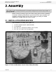


WHEATHEART - POWER SWING MANUAL 2. ASSEMBLY
ELECTRIC AND HYDRAULIC 2.3. POWER SWING ASSEMBLY
30802 R0 13
2.3. POWER SWING ASSEMBLY
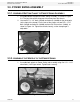
2.3.1. ASSEMBLE BOTTOM CLAMP TO POWER SWING ASSEMBLY
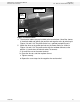
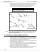
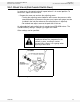
1. Assemble bottom clamp onto Power Swing assembly, as shown in Figure
2.4. The long side of the clamp must face away from the wheels.
2. Use two 5/8” x 1-1/2” bolts (19590) and locknuts (19600) for the pivot point
(at the front of the clamp). For the rear of the clamp, use two 5/8” x 1-1/2”
bolts (19590) and locknuts (19600) and two 5/8” flat washers (18096), as
shown in Figure 2.4. Tighten these bolts loosely, so the clamp angle is
adjustable.
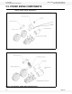
Figure 2.4 Adjustable Bottom Clamp Angle
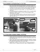
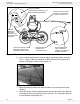
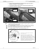
2.3.2. ASSEMBLE THE WHEELS TO THE POWER SWING
1. Assemble both wheels to Power Swing sub-assembly using five 1/2” x 1-1/2”
wheel bolts (19273) per wheel. Tighten bolts securely.
Figure 2.5 Power Swing Wheel Assembly