
User Manual

3. ASSEMBLY WHEATHEART - X13 SERIES AUGERS
3.3. ASSEMBLE THE MAIN AUGER TUBE X1374, X1384, X1394
28 30787 R1
3.3. ASSEMBLE THE MAIN AUGER TUBE
See Table 3.3. for a list of hardware required to assemble the main auger tube.
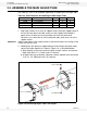
1. Align tube sections on a series of support stands, placing a support stand at
the end of each tube. If possible, make sure that support stand height is
equal across all tubes to ensure that tubes are level with each other.
Otherwise, use some form of shim to keep the tubes level across all of the
support stands.
Important: Always strap tubes to the support stands to prevent the tubes from rolling off the
stands and onto the floor.
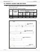
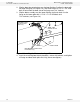
2. Working from the spout end (upper tube) to the discharge end (lower tube),
connect the tubes together as shown in Figure 3.4, as described below:
a. Align flightings to ensure a continual spiral of auger surface, and connect
flight shafts with 1/2” x 4” bolts and 1/2” locknuts.
b. As flight shafts are connected, slide tube sections together and secure with
7/16'' X 1-1/4'' GR8 bolts and 7/16” locknuts.
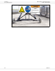
Figure 3.4 Connecting Auger Tubes and Flights
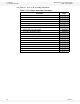
Table 3.3. Parts Required, Assembling the Main Auger Tube
Part Number Description X130-74 X130-84 X130-94
18974 1/2” x 4” bolts 3 3 4
17750 1/2” locknuts 3 3 4
18698 7/16'' X 1-1/4'' bolts 48 48 64
17593 7/16” locknuts 48 48 64
1/2” LOCKNUT
7/16” X 1-1/4” BOLTS
7/16”
1/2” X 4” BOLT
LOCKNUTS