
User guide


WHEATHEART - GHR & WHR GRAIN AUGERS 3. ASSEMBLY
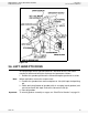
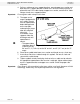
PTO-SD DRIVE MODEL 3.9. DISCHARGE SPOUT
30641 R1 27
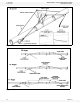
Figure 3.10
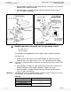
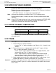
3.9. DISCHARGE SPOUT
1. Attach discharge spout with half tube clamps and 7/16” x 1-3/4” bolts and
locknuts as required. Note that some augers are equipped with weld-on
discharge spouts.
Note: If a safety spout is being used with this auger, the safety release door should be
on the left side of the auger, as determined when standing at intake, facing the
discharge end.
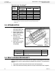
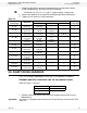
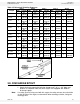
Table 3.5 Driveshaft Shielding Sequence
Auger Size/
Length
Step 1 Step 2 Step 3 Step 4 Step 5
Qty Length Qty Length Qty Length Qty Length Qty Length
8” x 31’ 1
42”
(1.07 m)
1
48”
(1.22 m)
1
42”
(1.07 m)
3
48”
(1.22 m)
1
42"
(1.07 m)
8” x 36’ 1
42”
(1.07 m)
1
48”
(1.22 m)
1
42”
(1.07 m)
4
48”
(1.22 m)
1
42"
(1.07 m)
8” x 41’ 3
42”
(1.07 m)
1
48”
(1.22 m)
1
42”
(1.07 m)
4
48”
(1.22 m)
1
42"
(1.07 m)
8" x 46’ 5
42”
(1.07 m)
4
60”
(1.52 m)
1
48”
(1.22 m)
-- -- -- --
8" x 51’ 2
42”
(1.07 m)
1
48”
(1.22 m)
6
60”
(1.52 m)
1
48”
(1.22 m)
-- --
8" x 56’ 2
42”
(1.07 m)
11
48”
(1.22 m)
1
42”
(1.07 m)
-- -- -- --
8" x 61’ 1
48”
(1.22 m)
2
42”
(1.07 m)
11
48”
(1.22 m)
1
42”
(1.07 m)
-- --
8" x 71’ 4
42”
(1.07 m)
1
48”
(1.22 m)
1
42”
(1.07 m)
11
48”
(1.22 m)
1
42"
(1.07 m)
10" x 31’ 1
42”
(1.07 m)
5
48”
(1.22 m)
1
42”
(1.07 m)
-- -- -- --
10" x 41’ 1
48”
(1.22 m)
3
42”
(1.07 m)
5
48”
(1.22 m)
1
42”
(1.07 m)
-- --
10" x 51’ 11
48”
(1.22 m)
1
42”
(1.07 m)
-- -- -- -- -- --
10" x 61’ 1
48”
(1.22 m)
2
42”
(1.07 m)
11
48”
(1.22 m)
1
42”
(1.07 m)
-- --
10" x 71’ 4
42”
(1.07 m)
1
48”
(1.22 m)
1
42”
(1.07 m)
11
48”
(1.22 m)
1
42"
(1.07 m)