
User guide

WHEATHEART - GHR & WHR GRAIN AUGERS 3. ASSEMBLY
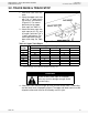
PTO-SD DRIVE MODEL 3.5. SHAFT DRIVE GEARBOX
30641 R1 23
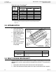
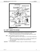
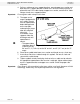
3. Slip lower driveshaft segments through bearings on lower tube section.
Install a Woodruff key, and slide into shaft connector.
• Driveshafts on 10" x 51’, 61’, and 71’ augers require a square key.
4. Place a few drops of oil at each driveshaft bearing to allow for break-in.
5. Tighten all set screws on shaft connectors.
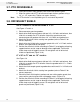
3.5. SHAFT DRIVE GEARBOX
The PTO-SD auger, depending on size, uses 1 of 2 gearbox assemblies.
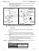
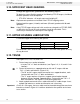
GEARBOX MOUNTING PROCEDURE FOR THE FOLLOWING AUGERS
Refer to Figure 3.7 and 3.8.
1. Remove chain and secure half of the chain coupler to driveshaft using a
Woodruff key.
Important: It is easier to fill gearbox with oil when flat. Fill half full only; do not overfill. See
Table 3.4.
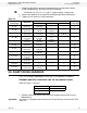
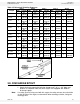
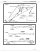
Table 3.3
Auger
Size/Length
Shaft Size
Driveshaft Sequence From Discharge End
No. of Strap-
On Bearings
1st 2nd 3rd
8" x 31’
1-1/4”
(3.18 cm)
7' 4-1/2”
(2.25 m)
--- --- 1
8" x 36’
1-1/4”
(3.18 cm)
4' 5-1/2”
(1.36 m)
3' 5-1/2”
(1.05 m)
--- 1
8" x 41’
1-1/4”
(3.18 cm)
3' 9-1/2”
(1.15 m)
4' 5-1/2”
(1.36 m)
4' 7”
(1.40 m)
2
8" x 46’
1-1/4”
(3.18 cm)
10' 2-1/2”
(3.12 m)
6' --- 2
8" x 51’
1-1/4”
(3.18 cm)
13' 10”
(4.21 m)
7' 4-1/2”
(2.25 m)
--- 2
8" x 56’
1”
(2.54 cm)
1' 3”
(0.38 m)
--- --- 0
8" x 61’
1-1/4”
(3.18 cm)
6' 4”
(1.92 m)
--- --- 0
8" x 71’
1-1/4”
(3.18 cm)
16' 4”
(4.98 m)
--- --- 0
10" x 31’
1-1/4”
(3.18 cm)
--- --- --- 0
10" x 41’
1-1/4”
(3.18 cm)
--- --- --- 0
10" x 51’
1-1/4”
(3.18 cm)
--- --- --- 0
10" x 61’
1-1/4”
(3.18 cm)
6' 4”
(1.92 m)
--- --- 0
8” x 31’ 8” x 46’
8” x 36’ 8” x 51’
8” x 41’