
User guide
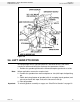

3. ASSEMBLY WHEATHEART - GHR & WHR GRAIN AUGERS
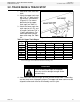
3.3. INTAKE HITCH PTO-SD DRIVE MODEL
22 30641 R1
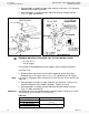
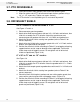
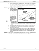
3.3. INTAKE HITCH
1. Clean dirt and paint
from lower flight stub
and intake bushing.
2. Attach intake hitch to
lower auger tube and
tighten securely.
3. Maintain 1/2” (1.27
cm) clearance
between bushing and
end of flight.
4. Attach clevis to intake
hitch with clevis pin
and gripclip.
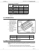
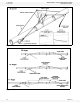
3.4. MULTI-STAGE DRIVESHAFT
Because some sections of the driveshaft are factory installed, please consult the
table below for correct sequence before completing installation. Then proceed as
follows:
1. Clean paint and dirt from driveshaft end and shaft connectors.
2. Slide shaft connector halfway onto the last pre-installed driveshaft segment.
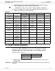
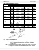
Table 3.2 Lower Track Stops
a
Auger
Length
From Intake End
Lower Track Stop Locations
Welded
Trackstop
1st Hole 2nd Hole
31’ 8”-10”
36’ 8”
41’ 8”-10”
46’ 8”
51’ 8”-10”
56’ 8”
61’ 8”-10”
71’ 8”-10”
a. Count from the lower intake end of auger. For example, “1st Hole”
refers to the first set of holes in the lower end of the track nearest the
intake end.
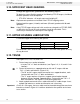
Part Size Amt.
Intake Hitch 7/16” x 1” bolt and locknut 6
Clevis Pin
5/8” for 8”
3/4” for 10”
1
Figure 3.6