
User guide
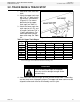
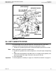

WHEATHEART - GHR & WHR GRAIN AUGERS 3. ASSEMBLY
PTO-SD DRIVE MODEL 3.2. TRACK SHOE & TRACK STOP
30641 R1 21
3.2. TRACK SHOE & TRACK STOP
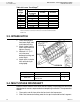
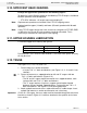
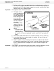
1. Slide roller track shoe onto
track.
2. Attach the upper track stop
with 7/16” x 1" bolts, heavy
flat washers, and locknuts
(Figure 3.5). For correct
positioning of the upper
track stop, see Table 3.1.
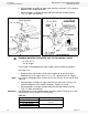
3. Attach the lower angle-iron
track stop (on 36’, 56’, and
61’ augers) with two 7/16” x
1" bolts and locknuts. For
correct positioning of the
lower track stop, see Table
3.2.
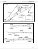
4. Slide track shoe along full length of track to make certain there is no binding
and that track ends are properly aligned. The upper and lower tracks must be
aligned to allow track shoe to roll smoothly over this joint.
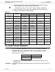
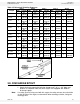
Table 3.1 Upper Track Stops
a
a. Count from upper discharge end of auger. For example, “1st Hole” refers to the first set of
holes in the upper end of the track nearest the discharge end.
Auger
Length
From Discharge End
Upper Track Stop Locations
1st Hole 2nd Hole 3rd Hole 4th Hole 5th Hole
31’ 8”-10”
36’ 8”
41’ 10" 8”
46’ 8”
51’ 10” 8”
56’ 8”
61’ 8”-10”
71’ 8”-10”
CAUTION
Failure to locate track stops in the proper
holes can result in damage to auger and/or
personal injury.
Figure 3.5