
Manual

3. ASSEMBLY WHEATHEART - GHR & WHR GRAIN AUGERS
3.6. DRIVESHAFT SHIELD GRAIN AUGERS SD
22 30662 R1
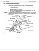
3.6. DRIVESHAFT SHIELD
Refer to Table 3.2 for the proper sequence for your particular auger. Shielding is
installed working from the gearbox assembly up to the discharge end.
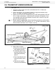
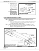
1. Attach drive shield to the shield mount with two 3/8” x 3/4” bolts and locknuts.
Then attach to gearbox with two 5/8” x 1" bolts and lockwashers.
2. Attach the chain coupler guard to gearbox base with two 3/8” x 3/4” bolts and
locknuts (Figure 3.7).
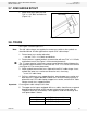
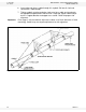
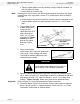
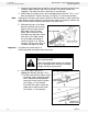
3. Place 42" driveshaft shields against gearbox and over chain coupler guard,
then secure with a shield strap and 2 self-tapping screws.
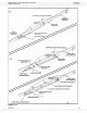
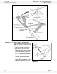
4. Position the driveshaft shields
according to Table 3.2,
overlapping at bearing
support brackets and at strap-
on bearings where applicable.
Fasten with shield straps and
self-tapping screws. Do not
tighten until all driveshaft
shields are positioned (Figure
3.8).
Figure 3.8
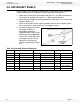
Table 3.2 Driveshaft Shielding Sequence
51’ 61’ 71’
STEP QTY LENGTH QTY LENGTH QTY LENGTH
1 1 42” (1.07 m) 4 42” (1.07 m) 1 42" (1.07 m)
2 5 48” (1.23 m) 5 48” (1.23 m) 5 48" (1.23 m)
3 1 60” (1.52 m) 1 60” (1.52 m) 1 60" (1.52 m)
4 4 48” (1.23 m) 4 48” (1.23 m) 4 48" (1.23 m)
5 1 42” (1.07 m) 1 42” (1.07 m) 1 60" (1.52 m)
6 - - - - 4 48" (1.23 m)
7 - - - - 1 42" (1.07 m)