
Owner's manual

WHEATHEART - SA FLEX AUGER 3. ASSEMBLY
71’ - 111’ 3.9. SCISSOR LIFT FRAME (71’–91’)
30651 R5 47
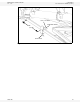
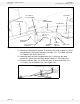
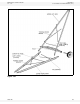
Figure 3.30
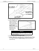
12. Remove the lifting device at point “B” and raise the auger at point “A” so the
transport brace (34) can be attached. Use eight 1/2” x 1-1/2” bolts (35) and
1/2” locknuts (36). See Figure 3.24.
13. Lower the auger until the transport brace (34) is resting on the lower
x-brace (21) and remove the lifting device at point “A”. See Figure 3.31.
14. Fasten the x-brace tubes (11) to the axle arms (8) and secure with 1/2” x
1-1/2” bolts (12) and locknuts (13). See Figure 3.24.
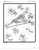
Figure 3.31
STABILIZER
BRACKET
STABILIZER
BRACE
SHORT
CROSSMEMBER
3/4” X 4-1/2”
BOLT
AXLE ARM
SIDE PLATE
5/8” X 2”
BOLT &
LOCKNUT
3/4” LOCKNUT
5/8” X 2-1/2”
BOLT &
LOCKNUT
5/8” X 1-3/4” BOLT
& LOCKNUT
FLEX FRAME
1” X 5” BOLT &
1” FLAT WASHER