
User Manual
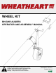

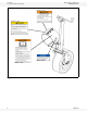
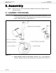


2. ASSEMBLY WHEATHEART - WHEEL KIT
2.1. ASSEMBLY PROCEDURE BH/GHR AUGERS
8 30736 R1
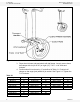
Figure 2.2
3. Place wheel kit onto tube and attach with half clamp. Loosely secure these
half clamps with six (for 8”/10”) or eight (13”) 7/16" x 1-1/4" bolts and
locknuts.
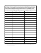
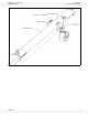
4. Position wheel kit as shown by "x" as defined in Table 2.1. Position half
clamps so that auger jack (wheel kit) is vertical. See Figure 2.3. Tighten the
7/16" locknuts.
Table 2.1
Auger x (in.) Auger x (in.) Auger x (in.)
BH 80-36 60 GHR 80-51 69 GHR 130-31 45.5
BH 80-41 72 GHR 80-56 80 GHR 130-36 45
BH 80-46 72 GHR 80-61 88 GHR 130-41 47
BH 80-51 72 GHR 80-71 94 GHR 130-51 49
BH 100-36 52 GHR 100-31 69 GHR 130-61 45
BH 100-41 65 GHR 100-41 63 GHR 130-71 50
GHR 80-31 69 GHR 100-51 63
GHR 80-36 76 GHR 100-61 89
GHR 80-41 69 GHR 100-71 88
GHR 80-46 76