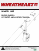
WHEEL KIT BH/GHR AUGERS OPERATOR AND ASSEMBLY MANUAL Read this manual before using product. Failure to follow instructions and safety precautions can result in serious injury, death, or property damage. Keep manual for future reference.
This product has been designed and constructed according to general engineering standardsa. Other local regulations may apply and must be followed by the operator. We strongly recommend that all personnel associated with this equipment be trained in the correct operational and safety procedures required for this product. Periodic reviews of this manual with all employees should be standard practice. For your convenience, we include this sign-off sheet so you can record your periodic reviews.
WHEATHEART - WHEEL KIT BH/GHR AUGERS TABLE OF CONTENTS 1. Safety .................................................................................................................................... 1.1. Safety Decal Locations............................................................................................. 1.1.1. Decal Installation/Replacement .................................................................. 1.1.2. Decal Locations ................................................................
WHEATHEART - WHEEL KIT BH/GHR AUGERS 4 30736 R1
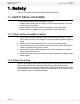
WHEATHEART - WHEEL KIT BH/GHR AUGERS 1. SAFETY 1.1. SAFETY DECAL LOCATIONS 1. Safety Refer to your auger manual for complete safety instructions. 1.1. SAFETY DECAL LOCATIONS • Keep safety decals clean and legible at all times. • Replace safety decals that are missing or have become illegible. See decal location figures that follow. • Replaced parts must display the same decal(s) as the original part. • Safety decals are available from your distributor, dealer, or factory. 1.1.1.
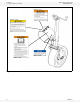
1. SAFETY 1.1. SAFETY DECAL LOCATIONS WHEATHEART - WHEEL KIT BH/GHR AUGERS DECAL 17113 DECAL 17109 DECAL 19960 DECAL 17096 Figure 1.
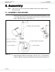
WHEATHEART - WHEEL KIT BH/GHR AUGERS 2. ASSEMBLY 2.1. ASSEMBLY PROCEDURE 2. Assembly Note: GHR Series only: Ensure that frame stabilizer brackets are installed, refer to operator manual. 2.1. ASSEMBLY PROCEDURE 1. Bolt the wheel jack assembly to the castor wheel assembly using four 7/16" x 1-1/4" bolts and locknuts. The sandwich plate connects under the two castor plates. Tighten and secure. See Figure 2.1. Figure 2.1 2. Attach transport handle to castor plates.
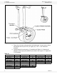
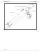
2. ASSEMBLY 2.1. ASSEMBLY PROCEDURE WHEATHEART - WHEEL KIT BH/GHR AUGERS Figure 2.2 3. Place wheel kit onto tube and attach with half clamp. Loosely secure these half clamps with six (for 8”/10”) or eight (13”) 7/16" x 1-1/4" bolts and locknuts. 4. Position wheel kit as shown by "x" as defined in Table 2.1. Position half clamps so that auger jack (wheel kit) is vertical. See Figure 2.3. Tighten the 7/16" locknuts. Table 2.
WHEATHEART - WHEEL KIT BH/GHR AUGERS 2. ASSEMBLY 2.1. ASSEMBLY PROCEDURE Figure 2.
2. ASSEMBLY 2.1.
WHEATHEART - WHEEL KIT BH/GHR AUGERS 3. OPERATION AND TRANSPORT 3.1. OPERATION 3. Operation and Transport 3.1. OPERATION 1. Place wheel kit in operation position by disengaging spring-loaded lock pin and turn wheel kit counterclockwise. 2. Secure wheel kit in hole in mounting bracket so that it is roughly perpendicular to the ground. 3. Disengage transport handle by removing snap pin and lock plate and reinserting snap pin, see Figure 3.1. 4.
3. OPERATION AND TRANSPORT 3.2. TRANSPORT WHEATHEART - WHEEL KIT BH/GHR AUGERS 3.2. TRANSPORT 1. Place the wheel kit in transport position by disengaging spring-loaded lockpin and turn wheel kit clockwise. Secure wheel kit in second hole in half clamp mounting bracket. See Figure 3.2. NOTICE Damage to equipment could result from not placing wheel kit in transport position prior to transport. 2. Place jack handle in transport position, use snap pin and lock plate to secure jack handle. See Figure 3.2.
WHEATHEART - WHEEL KIT BH/GHR AUGERS 4. MAINTENANCE AND STORAGE 4.1. OFF-SEASON STORAGE 4. Maintenance and Storage 4.1. OFF-SEASON STORAGE 1. Raise wheel to full up and secure in transport position. 2. Inspect unit for damage and note any repairs required. Order replacement parts from your dealer. 3. Check tire pressure and inflate to 45 psi (310 kPa). 4.2. TO PREPARE FOR USE AFTER STORAGE Important: 1. Check tire pressure and inflate according to recommendation if necessary, see Maintenance section.
4. MAINTENANCE AND STORAGE 4.3.
LIMITED WARRANTY Wheatheart warrants to the buyer that the new machinery is free from defects in material and workmanship. This warranty is only effective for any new machinery that has not been altered, changed, repaired, or treated since its delivery to the buyer, other than by Wheatheart or its authorized dealers or employees, and does not apply to accessories, attachments, tools, or parts sold or operated with the new machinery if they have not been manufactured by Wheatheart.
Wheatheart Part of the Ag Growth International Inc. Group P.O. Box 39 Rosenort, Manitoba, Canada R0G 1W0 Phone: (866) 467-7207 (Canada & USA) Fax: (866) 768-4852 website: www.wheatheart.com email: sales@wheatheart.com © Ag Growth International Inc.