
Instruction Manual


WHEATHEART - GRAIN AUGER EMD 3. ASSEMBLY
GHR 80 X 31’-71’ & 100 X 31’-71’ 3.2. TRACK SHOE & TRACK STOP
30642 R0 17
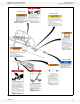
3.2. TRACK SHOE & TRACK STOP
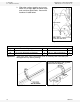
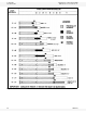
1. Slide roller track shoe onto track.
2. Attach the upper angle-iron track stop
with 7/16” x 1" bolts, heavy flat
washers, and locknuts (Figure 3.4). For
correct positioning of the upper track
stop, see Table 3.1.
3. Attach the lower angle-iron track stop
(on 36’, 56’, and 61’ augers) with two
7/16” x 1" bolts and locknuts. For
correct positioning of the lower track
stop, see Table 3.2.
Figure 3.4
Table 3.1 Upper Track Stops
a
Auger
Length
From Discharge End
Upper Track Stop Locations
1st Hole 2nd Hole 3rd Hole 4th Hole 5th Hole
31’ 8”-10” - - - -
36’ - 8” - - -
41’ 10" - - 8” -
46’ - - - 8” -
51’ - 10” - - 8”
56’ - 8” - - -
61’ - - 8”-10” - -
71’ - - - 8”-10” -
a. Count from upper discharge end of auger. For example, “1st Hole” refers to the first set of holes in the upper end
of the track nearest the discharge end.
Table 3.2 Lower Track Stops
a
a. Count from the lower intake end of auger. For example, “1st Hole”
refers to the first set of holes in the lower end of the track nearest the
intake end.
Auger
Length
From Intake End
Lower Track Stop Locations
Welded Track
Stop
1st Hole 2nd Hole
31’ 8”-10” - -
36’ - 8” -
41’ 8”-10” - -
46’ 8” - -
51’ 8”-10” - -
56’ - - 8”
61’ - 8”-10” -
71’ 8”-10” - -
CAUTION
Failure to locate track stops in the proper
holes can result in damage to auger and/or
personal injury.