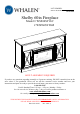
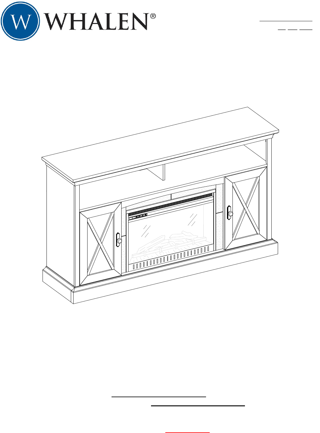
LOT NUMBER: DATE PURCHASED: / / Shelby 60in Fireplace Model # WSF60SY26C # WSF60SY26M ADULT ASSEMBLY REQUIRED If you have any questions regarding assembly or if parts are missing, DO NOT return this item to the store where it was purchased. Please call our toll-free customer service number and have your instructions and parts list ready to provide the model name, part name or factory number: 1-866-942-5362 Pacific Standard Time: 8:30 a.m. - 4:30 p.m.
QUALITY GUARANTEE We are confident that you will be delighted with your Whalen Furniture purchase. Should this product be defective in workmanship or materials or fail under normal use, we will repair or replace it for up to one (1) year from date of purchase. Every Whalen Furniture product is designed to meet your highest expectations. We guarantee that you will immediately see the value of our fine furniture.
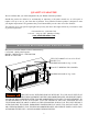
IMPORTANT Before you begin: Open, identify and count all parts prior to assembly. Lay out parts on a flat and nonabrasive surface. You will need the parts identified on page 4 and 5 of this instruction manual. NOTE: IT IS VERY IMPORTANT TO USE GLUE WITH THE DOWELS. EXCESS GLUE CAN BE WIPED OFF WITH A DAMP CLOTH. Insert Dowel at least half way by tapping lightly with a rubber mallet (not included), IF NECESSARY. CAM LOCK SYSTEM OPERATION HOW THE KNOCK DOWN (KD) ASSEMBLY SYSTEM WORKS 1.
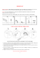
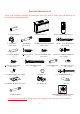
Parts and Hardware List Please read completely through the instructions and verify that all listed parts and hardware are present before beginning assembly.
Parts and Hardware List Please read completely through the instructions and verify that all listed parts and hardware are present before beginning assembly.
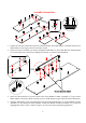
Assembly Instructions B 2 C G F 1. Unpack the unit and confirm that you have all the hardware and required parts. Assembly the unit on a carpeted floor or the empty carton to avoid any scratch. 2. Secure screw the Cam Bolts (2) into the designated small holes on the Fixed Shelf (B), Bottom Panel (C), Lower Partitions (F and G) by a Phillips screwdriver, as shown in the illustration. I 1 3 B 3. Insert two Wood Dowels (3) into the inner holes of the Middle Crossbar Assembly (I).
Assembly Instructions O 1 3 C 5. Align and attach the Base Rear Stretcher (O) to the Bottom Panel (C) by using three wood dowels (3) and four cam locks (1). J 1 3 F K G 6. Align and attach the Middle Left Stringer (J) to the Left Lower Partition Panel (F) by using two Wood Dowels (3) and three Cam Locks (1). 7. Repeat last step to combine the Middle Right Stringer (K) with the Right Lower Partition Panel (G) together.
Assembly Instructions K B 3 G J F 8. Insert four Wood Dowels (3) into the inner holes of the Lower Partition Panels (F and G) and attach them to the Fixed Shelf (B) by engaging four Cam Locks (1). 3 G F 3 C 4 4 9. Insert four Wood Dowels (3) into the bottom holes of the Lower Partition Panels (F and G) and position the Bottom Panel (C) onto the inserted Wood Dowels (3). Attach the Bottom Panel (C) in place by using four 1-1/2” Wood Screws (4).
Assembly Instructions D 2 E 10. Securely screw the Cam Bolts (2) into the designated small holes on the Left and Right Side Panels (D and E) by a Phillips screwdriver. 4 4 D E 3 N 3 M 11. Insert three Wood Dowels (3) into the inner holes on the Left Bottom Molding (M) and fasten it to the Left Side Panel (D) with six 1-1/2” Wood Screws (4). 12. Repeat last step to combine the Right Bottom Molding (N) with the Right Side Panel (E) together.
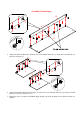
Assembly Instructions E 1 B C O D 13. Insert ten Wood Dowels (3) into the large holes on Bottom Panel and Base Rear Stretcher (C and O) and Fixed Shelf (B) at both ends. 14. Align the large holes on the Left Side Panel (D) with the inserted Wood Dowels (3). Firmly press them together and fasten it in place by engaging five Cam Locks (1). 15. Repeat last step to attach Right Side Panel (E) at the other end. 1 E C D P 16.
Assembly Instructions 4 E P C 4 D 17. Fasten the Base Front Stretcher (P) to the Side Panels (D and E) with four 1-1/2” Wood Screws (4). 3 L 4 3 P C 4 18. Insert four Wood Dowels (3) into the inner holes on Base Front Molding (L) and attach it to the Base Front Stretcher (P) using eight 1-1/2” Wood Screws (4).
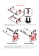
Assembly Instructions I I 11 6 K J 7 J/K F G 19. Stand the assembled unit upright. 20. Fasten the Middle Crossbar Assembly (I) to the Middle Left and Right Stringers (J and K) by attaching two Metal Brackets (11) at the joints, using two 5/8” Black Screws (7) per Bracket. 21. Insert two 1” Screws (6) through the countersunk holes on the Middle Left and Right Stringers (J and K) and screw into the Middle Crossbar Assembly (I) as shown. 2 B 22.
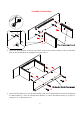
Assembly Instructions H 1 B 3 23. Insert one Wood Dowel (3) into the inner hole of the Partition Panel (H) and attach it to the Fixed Shelf (B) by using two Cam Locks (1). 2 A 24. Securely screw six Cam Bolts (2) into the designated small holes on Top Panel (A) by a Phillips screwdriver.
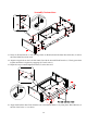
Assembly Instructions A 3 H 1 D E 25. Insert five Wood Dowels (3) into the top inner holes of the Upper Partition Panel (H) and Side Panels (D and E). Position the Top Panel (A) onto the inserted Wood Dowels (3) and fasten it in place with six Cam Locks (1). A T 8 U U 26. Pick up the Upper Back Panel (T) and align the pre-drilled holes against the upper long edge with the pilot holes on the back stretcher of Top Panel (A).
Assembly Instructions S 13 E G D F 13 S S 28. Insert four Shelf Supports (13) into the holes at your desired height inside each compartment. Tilt and rest the Adjustable Shelves (S) onto the Shelf Supports (13). Q Wood panel (Pre-attached) R Glass panel Note: The doors are shipped with Wood Door Panel. You can keep the door as it is or interchange with Glass Door Panel (R) depending on your configuration. 29.
Assembly Instructions 9 9 17 17 15 x2 Q 14 30. Extend the Door Hinges (17) and rest the hinge cups onto the cutouts of one Door Panel (Q). Secure the Door Hinges (17) in place by using two 5/8” Zinc Screws (9) in each. 31. Attach one Knob (14) to the front side of the Door with one Knob Bolt (15). 32. Repeat the same procedure with the other Door Panel (Q). E Q 17 D 9 Q 33.
Assembly Instructions Q 16 12 Q 16 Q 36. Plug the Cam Lock Covers (12) onto the visible cams locks to conceal the cams. 37. Stick the Rubber Bumpers (16) on the outer corners of Doors (Q) as shown. I Electric Firebox C 38. Lift the fireplace insert carefully into the back of the assembled mantel and center it in the opening. DO NOT drag the insert across the Bottom Panel (C) as it may scratch the unit.
Assembly Instructions Electric 10 Firebox 10 I V 39. Align and attach the Firebox Support (V) to the Bottom Panel (C) by inserting two 2” Self-tapping Screws (10) through the countersunk holes and screw into place. 5 A 5 A A NOTE: You must install the Acrylic TV Stopper to prevent the TV from tipping when placing your flat panel television directly on the console. 40.
Assembly Instructions Tools required (not provided): Phillips screwdriver, stud finder, power drill and 3 mm/0.1 in drill bit. 42. Ask for assistance to position the assemble fireplace at the desired location against a wall. If necessary, adjust the pre-attached Floor Levelers at the bottom of the Base Front Molding (L) to level the unit. Now, follow the instructions printed on the plastic bag containing the Tipping Restraint Hardware to attach the tip-over restraints to the unit and the wall.
Care and Maintenance Use a soft, clean cloth that will not scratch the surface when dusting. Use of furniture polish is not necessary. Should you choose to use polish, test first in an inconspicuous area. Using solvents of any kind on your furniture may damage the finish. Never use water to clean your furniture as it may cause damage to the finish. Always use coasters under beverage glasses and flowerpots. Liquid spills should be removed immediately.