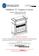
LOT NUMBER: DATE PURCHASED: / / Middleton 32” Fireplace Console Model # WSF32WV23-DB # WSF32WV23-WA ADULT ASSEMBLY REQUIRED If you have any questions regarding assembly or if parts are missing, DO NOT return this item to the store where it was purchased. Please call our toll-free customer service number and have your instructions and parts list ready to provide the model name, part name or factory number: 1-866-942-5362 Pacific Standard Time: 8:30 a.m. - 4:30 p.m.
MAXIMUM RECOMMENDED WEIGHT LOADS MANUFACTURER: Whalen Furniture Manufacturing CATALOG: Middleton 32” Fireplace Console MODEL # WSF32WV23-DB / WSF32WV23-WA MADE IN CHINA FITS UP TO MOST 99.06 cm / 39” FLAT PANEL TVs MAXIMUM LOAD 27 kg / 60 lb PLACE TV BEHIND THE STOPPER MAXIMUM LOAD 22.7 kg / 50 lb THIS UNIT IS NOT INTENDED FOR USE WITH CRT TVS. USE ONLY WITH FLAT PANEL TVS AND AUDIO/VIDEO EQUIPMENT MEETING RECOMMENDED SIZE AND WEIGHT LIMITS.
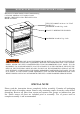
IMPORTANT Before you begin: Open, identify and count all parts prior to assembly. Lay out parts on a flat and nonabrasive surface. You will need the parts identified on page 4 and 5 of this instruction manual. NOTE: IT IS VERY IMPORTANT TO USE GLUE WITH THE DOWELS. EXCESS GLUE CAN BE WIPED OFF WITH A DAMP CLOTH. Insert Dowel at least half way by tapping lightly with a rubber mallet (not included), IF NECESSARY. 1 2 3 X 4 X CAM LOCK SYSTEM OPERATION HOW THE KNOCK DOWN (KD) ASSEMBLY SYSTEM WORKS 1.
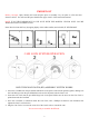
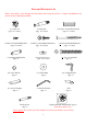
Parts and Hardware List Please read completely through the instructions and verify that all listed parts and hardware are present before beginning assembly. A- Top Panel (Qty. 1) D- Upper Side Panel (Qty. 2) G- Middle Crossbar (Qty. 1) B- Base (Qty. 1) C- Center Shelf (Qty. 1) E- Lower Left Side Panel (Qty. 1) H- Back Panel (Qty. 1) Fireplace Insert (Qty. 1) F- Lower Right Side Panel (Qty. 1) I- Firebox Support (Qty. 1) Remote Control with Battery (Qty.
Parts and Hardware List Please read compl etely through the instructions and verify that all list ed parts and hardware are present before beginning assembly. (1) Cam Lock (Qty. 16+1 extra) (2) Cam Bolt (Qty. 16+1 extra) (3) 8 mm x 30 mm Wood Dowel (Qty. 27+1 extra) (4) M3.5 x 12 mm Flat Head Screw (Qty. 4+1 extra) (5) M3.5 x 15 mm Washer Head Screw (Qty. 14+1 extra) (6) M4 x 64 mm Flat Head Screw (Qty. 3+1 extra) (7) Straight Metal Bracket (Qty. 2) (8) Cam Lock Cover (Qty.
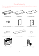
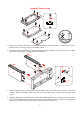
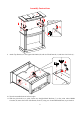
Assembly Instructions 2 A B C 1. Unpack the unit and confirm that you have all the hardware and required parts. Assemble the unit on a carpeted floor or the empty carton to avoid any scratch. 2. Securely screw the Cam Bolts (2) into the designated plastic bushings on the Top Panel (A), the Base (B) and the Center Shelf (C) using a Phillips screwdriver. UP UP F 3 E B 1 3. Insert six Wood Dowels (3) into the bottom inner holes on the Lower Side Panels (E and F).
Assembly Instructions 6 6 6 G 3 3 C 5. Glue two Wood Dowels (3) into the inner holes of the Middle Crossbar (G) and attach it to the front edge of the Center Shelf (C) with three 63 mm Flat Head Screws (6). 3 C F B E 6. Attach the previous assembly (C and G) to Lower Side Panels (E and F) with six Wood Dowels (3) and four Cam Locks (1).
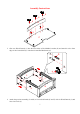
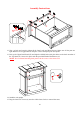
Assembly Instructions C 2 7. Ask for assistance to stand the unit upright. Securely screw four Cam Bolts (2) into the plastic bushings on the Center Shelf (C). D D C 8. Attach the Upper Side Panels (D) to the Center Shelf (C) with six Wood Dowels (3) and four Cam Locks (1).
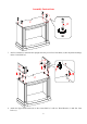
Assembly Instructions A D D 1 9. Attach Top Panel (A) to the Upper Side Panels (D) with six Wood Dowels (3) and four Cam Locks (1). F G E 10. Turn the assembled unit at its front edges. 11. With the pilot holes as a guide, fasten two Straight Metal Brackets (7) at the joints where Middle Crossbar (G) meets the Lower Side Panels (E and F), using two 12 mm Flat Head Screws (4) per bracket.
Assembly Instructions H C 5 D 12. Now, go back and securely tighten all the Cam Locks and Wood Screws. Make sure all the parts are tight and there are no gaps between the parts. This will help keep the unit square. 13. Pick up the Upper Back Panel (H) and align the drilled holes with pilot holes on the back stretcher of the Top Panel (A). Secure it in place with the provided Washer Head Screws (5). NOTE: We recommend attaching back panel with the screws at the corners first. 8 14.
Assembly Instructions B 16. Lift the fireplace insert carefully into the back of the assembled mantel and center it in the opening. DO NOT drag the insert across the Base (B) as it may scratch the unit. The rubber bumper is against the firebox 3 5 I 11 10 12 9 B 17. Using the pilot holes as a guide, align and attach two L-shaped Metal Braces (12) to the Base (B) by screwing one Washer Head Screw (5) in each. 18.
Assembly Instructions NOTE: To prevent your TV from tipping, you must follow these instructions if you place a TV on top of your console. Otherwise, skip to “Step 20”. 19. Remove the paper backing from the Acrylic Stopper (13), then properly align the Acrylic Stopper into the cut-out on the acrylic stopper template on the Top Panel (A). Press down on the acrylic stopper to help adhesion. 20.
Assembly Instructions Tools required: Phillips screwdriver, stud finder, power drill and 1/8” drill bit. 21. Position the console at the desired location against a wall. If necessary, adjust the pre-attached floor levelers until the unit is level. 22. Follow the instructions printed on the plastic bag containing the tipping restraint hardware to attach the tip-over restraints to the unit and the wall. NOTE: The tipping restraint hardware included is for wooden stud wall construction.
Care and Maintenance Use a soft, clean cloth that will not scratch the surface when dusting. Use of furniture polishes is not necessary. Should you choose to use polishes, test first in an inconspicuous area. Using solvents of any kind on your furniture may damage the finish. Never use water to clean your furniture as it may cause damage to the finish. Always use coasters under beverage glasses and flowerpots. Liquid spills should be removed immediately.