USB Controlled DMX interface ing a PC and USB Control DMX fixtures us interface. 2 ction that outputs all 51 fun t tes Stand-alone .
Features & specifications Features : This unit can control DMX fixtures using a PC and USB interface Test software and "DMX Light Player" software is included, a DLL is provided to write you own software Furthermore there is a stand-alone test function that outputs all 512 channels at a time, with adjustable levels Specifications : Connected and powered through USB 512 DMX channels with 256 levels each 3 pin XLR—DMX output connector Windows 98SE or higher compatible DLL inclu
Assembly hints 1. Assembly (Skipping this can lead to troubles ! ) Ok, so we have your attention. These hints will help you to make this project successful. Read them carefully. 1.1 Make sure you have the right tools: A good quality soldering iron (25-40W) with a small tip. Wipe it often on a wet sponge or cloth, to keep it clean; then apply solder to the tip, to give it a wet look. This is called ‘thinning’ and will protect the tip, and enables you to make good connections.
Assembly hints Use the check-boxes to mark your progress. Please read the included information on safety and customer service * Typographical inaccuracies excluded. Always look for possible last minute manual updates, indicated as ‘NOTE’ on a separate leaflet. 1.
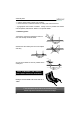
Construction 1. Diode (check the polarity) 4. IC sockets D... CATHODE IC1 : 8P IC2 : 28P D1 : 1N4148 2. Zener diodes (check the polarity) 5. Capacitors c... ZD... CATHODE ZD1 : 6,2V (6V2) ZD2 : 6,2V (6V2) 3. 1/4W Resistors. R... C1 C2 C3 C4 C5 C6 C7 : 33pF : 33pF : 100n : 100n : 100n : 100n : 220n (33) (33) (104, 0.1, u1) (104, 0.1, u1) (104, 0.1, u1) (104, 0.1, u1) (224) 6. Transistors T1 : BC327 T2 : BC337 R1 : 10K - 0polarity) - 3 - B) 1.
Construction 8. USB connector 13. Push button * SK4 : USBB90 SW1 9. Polyswitch resettable fuses 14. Battery holder * 4mm M3 BOLT Mount the battery clip on the PCB using the 4mm M3 bolt and M3 nut. FS1 : 3A /60Vdc FS2 : 3A/60Vdc M3 NUT The PTC resistor resets automatically and protects your circuit permanently. 15. LEDs. Check the polarity! 10. Electrolytic capacitor. Check the polarity ! C8 : 4,7µF LD... C... 23mm 30mm 0.
Construction 17. IC’s check the position ! 18. CE/FCC Sticker Affix the supplied CE/FCC sticker on the bottom of the housing, see fig. 1.0. Velleman SFCC Tested to comply with FCC standards for home and office use IC1 : SN75176BP or MAX485 FIG. 1.0 IC2 : VK8062 (programmed PIC18F2550)* 19. XLR socket. Solder the 3-pole female print connector to the XLR connector using the figure below to check the accuracy of the connections (see fig. 2.0 & 3.0). Brown Brown Red Fig. 2.
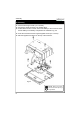
Assembly 20. Assembly Fix the PCB using 4 screws ( 2.9 x 6,5mm). Connect the wired connector to 3p header (SK3). If stand alone function is used, connect the battery to the connector and insert the battery in the battery compartment as indicated in fig. 5.0. Close the enclosure with the longest supplied screws (2.9 x 9.5mm). Affix the supplied front sticker on the top of the enclosure. Fig. 5.0 Remark : Respect your national and local laws when disposing of empty batteries.
Software installation and test 21. Software installation Browse through the CD and open the K8062 folder. Check the appropriate PDF files for further information. The ‘light player’ software is installed in the folder by default: c:\program files\DMX This is a screen shot of the DMX_demo software, used tot test the unit or to make some simple shows. You will find the latest version of the software on our website 22.
PCB 23.
Schematic diagram 24.
VELLEMAN NV Legen Heirweg 33, B-9890 GAVERE Belgium (Europe) Modifications and typographical errors reserved © Velleman Kit nv H8062IP - 2014 - ED1 (rev 6.