
User Manual


4
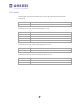
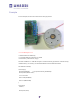
Pin Layout
All 6 analogue input pins are available. They can also be used as digital pins (pins #14
through 19)
digital pin
function
#2, #13
not used
Following pins are only used if the DC/stepper is in use:
digital pin
function
#11
DC motor #1/stepper #1 (activation/speed control)
#3
DC motor #2/stepper #1 (activation/speed control)
#5
DC motor #3/stepper #2 (activation/speed control)
#6
DC motor #4/stepper #2 (activation/speed control)
Following pins are only used if any DC/steppers are in use:
digital pin
function
#4, #7, #8, #12
driving the DC/stepper motors via the 74HC595 serial-to-parallel latch
Following pins are only used if that particular servo is in use:
digital pin
function
#9
servo #1 control
#10
servo #2 control