
User Manual
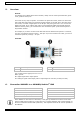
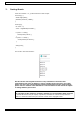
Table Of Contents

VMA347
V. 01 – 12/02/2020 3 ©Velleman nv
5. Overview
General
The VMA347 is an LM393 speed sensor module, widely used in motor speed detection, pulse
count, position control, etc.
The sensor is very easy to operate: To measure the speed of a motor, make sure the motor
has a disk with holes. Each hole should be equally spaced on the disk. Every time the sensor
sees a hole, it creates a digital pulse on the D0 pin. This pulse goes from 0 V to 5 V and is a
digital TTL signal. If you capture this pulse on a development board and calculate the time
between the two pulses, you can determine the revolutions speed: (time between pulses X
60)/number of holes.
For example, if you have one hole in the disk and the time between two pulses is 3 seconds,
you have a revolutions speed of 3*60 = 180 rpm. If you have 2 holes in the disk, you have a
revolutions speed of (3*60/2) = 90 rpm.
Overview
1
opto-interrupter
3
power LED
2
LM393
4
data LED
VCC: module power supply from 3.0 to 12 V.
GND: ground.
D0: digital signal of the output pulses.
A0: analogue signal of the output pulses. Output signal in real-time (usually not used).
6. Connection VMA451 to a VMA100/Arduino
®
UNO
VMA100/Arduino
®
UNO
VMA347
VCC
V
GND
G
any digital I/O pin
D0
A0
If the VMA347 is used close to a DC motor, it may pick-up interferences with as result more
pulses on DO as there really are. In this case use a ceramic capacitor with a value between 10
and 100 nF between DO and GND (debounce). This capacitor should be as close as possible to
the VMA437.