
User Manual
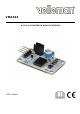


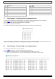


Table Of Contents

VMA344
V. 01 – 10/04/2019 4 ©Velleman nv
1
light sensor
9
AIN0
2
VCC
10
AIN1
3
GND
11
AIN2
4
SDA
12
AIN3
5
SCL
13
potentiometer
6
power LED
14
temperature sensor
7
signal LED
15
jumpers P4, P5, P6
8
AOUT
7. Test Example 1: Reading the 4 Analogue Inputs
1. Make the connections as mentioned before. You will not need the A0 connection for this example.
2. Click here to download and extract VMA344 Test file from our website.
3. Run the Arduino
®
IDE and load the VMA344 test software.
4. Compile and upload to the VMA100.
5. Open the serial monitor and if everything works well You should have a similar result:
The first row is AIN0, connected to the photodiode (if the jumper is set). Change the light intensity and you will
see the value changing. The third row is “floating” as nothing is connected to AIN2.
8. Test Example 2: Controlling the Analogue Input
1. Connect the AOUT to the A0 of your VMA100.
2. Click
here to download, extract and load the VMA344 Output file.
3. On the serial monitor you will see how the AOUT voltage increases step by step.
As AOUT is connected to LED D2, you will notice that the LED will follow the AOUT voltage.