
Datasheet


TLP281,TLP281-4
4 2019-06-17
© 2019
Toshiba Electronic Devices & Storage Corporation
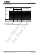
Electrical Characteristics
(Ta = 25°C)
CHARACTERISTIC SYMBOL TEST CONDITION MIN TYP. MAX UNIT
LED
Forward Voltage V
F
I
F
= 10 mA 1.0 1.15 1.3 V
Reverse Current I
R
V
R
= 5 V
—
— 10 μA
Capacitance C
T
V = 0 V, f = 1 MHz
—
30 — pF
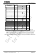
DETECTOR
Collector-Emitter Breakdown Voltage V
(BR) CEO
I
C
= 0.5 mA 80
— —
V
Emitter-Collector Breakdown Voltage V
(BR) ECO
I
E
= 0.1 mA 7
— —
V
Collector Dark Current
(Note 1)
I
CEO
V
CE
= 48 V
—
0.01 0.1
μA
Ambient Light Below (100 ℓx)
(Note 2)
—
2 10
V
CE
= 48 V, Ta = 85 °C
—
2 50
μA
Ambient Light Below (100 ℓx)
(Note 2)
—
4 50
Capacitance (Collector to Emitter) C
CE
V = 0 V, f = 1 MHz
—
10 — pF
Note 1: Because of the construction,leak current might be increased by ambient light.
Please use photocoupler with less ambient light.
Note 2: Irradiation to marking side using standard light bulb.
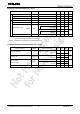
Coupled Electrical Characteristics
(Ta = 25°C)
CHARACTERISTIC SYMBOL TEST CONDITION MIN TYP. MAX UNIT
Current Transfer Ratio I
C
/I
F
I
F
= 5 mA, V
CE
= 5 V
Rank GB
50
—
600
%
100
—
600
Saturated CTR I
C
/I
F(sat)
I
F
= 1 mA, V
CE
= 0.4 V
Rank GB
— 60
—
%
30
— —
Collector-Emitter
Saturation Voltage
V
CE(sat)
I
C
= 2.4 mA, I
F
= 8 mA
— —
0.4
V
I
C
= 0.2 mA, I
F
= 1 mA
Rank GB
—
0.2 —
— —
0.4
Off-State Collector Current I
C(off)
V
F
= 0.7 V, V
CE
= 48 V
—
—
10 μA