
User's Manual


10
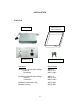
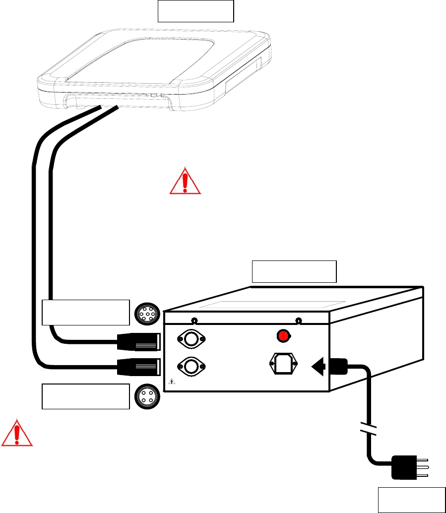
Deactivator Components and Connections
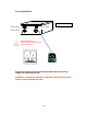
As shown in Figure 1, the deactivator consists of a detect/deactivator antenna
pad, power and control box. The cables used and connections are shown in
the following diagram. The antenna pad can be installed flush to the counter
with the flush mount kit.
POWER
AN2-HIGH VOLTAGE !
CARE IN OPERATION
AN2
AN1
AC INPUT
ON
OFF
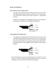
7-pin Connector
4-pin Connector
Power Plug
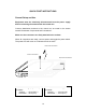
Always match the antenna type (read the label on
the plastic housing) with control box input voltage
type before connecting them; make sure they are
matched.
An 110VAC antenna cannot be connected to a
220VAC control box, nor vice versa.
Antenna
Control Box
A
n 1
A
n 2
HIGH VOLTAGE – HANDLE WITH CARE!
Equipment must be electrically disconnected from
the branch-circuit supply when connecting the
antenna with the control box.