
User's Manual


Quick Start for System Connections
A Floor Guard system consists of a smart power supply (WG SPS-24), a Floor Guard Control
Unit and a Floor Antenna.
The smart power supply has a 6-pins 24vac outputs that can only power the Floor Guard
Control Unit through 24vac and also communicate with the control unit for some tuning control
and remote alarm display features.
The PLCU is powered and controlled by the WG SPS-24 power supply unit. Also the control
unit has an 8-conductors cable with two 4pins connectors assembled on one end to connect
to the Floor Guard Control Unit transceiver board. One of the connectors is 4-pins connector
for TX transmitting signals from the Control Unit to drive a loop antenna coil and a figure8
antenna coil in Floor Guard antenna. The other connector is a 4-pins connector for RX signals
from the Control Unit to receive signals from Floor Guard ferrite antennas.
Notice: Both the TX and RX cables has wire orders that follow the pin and wire color
mapping and can not be transpose with the order.
Additional installation procedures are shown in greater detail in the following sections.
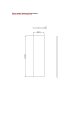
Floor Guard
Buried antenna
6
p
cable
Control Unit
Ferrite AN1: brown and red wires
Ferrite AN2: orange and yellow wires
Connections Legend
WG SPS-24 6p Cable
TX Loop and Figure8 Driving Cable
RX Ferrite Rod Signal
Figure8 AN: blue and green wires
Loop AN: white and black wires
WGSPS
-
24
110/220vac
Maximum Connection Length:4 meters