
User's Manual


Pro-Guard & Uni-Guard Installation Manual
6
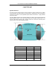
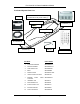
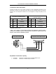
Transformer Cable Connection
Connect the three pins of the power connector to the corresponding terminals of the
transformer connector. The ground pins from both must be connected, but the 0V and 24V
terminals from the step-down transformer can be swapped to change the polarity of the
system.
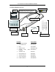
3-Pin Power Connector Layout
3-Terminal Transformer
Connector Layout
Pin Function Color Pin Function Color
1
“N or L“
*
Blue/Brown 1 0V Blue/Brown
2 Ground Green w/Yellow Stripe 2 Ground Green w/Yellow Stripe
3
“L or N” *
Brown/Blue 3 24V Brown/Blue
(180 degrees phase switch)
* Note: Pin 1 and Pin 3 of the power connector are equivalent to former N and L
terminals for 110/220vac systems. Switching them will switch the system’s phase 180
degrees; same as former 110/220vac systems.
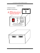
Step-Down Transformer Capacity
• Pro-Guard: Maximum 1 Transformer per Transmitter/Receiver pair.
• Uni-Guard: Maximum 1 Transformer per Uni-Guard.
Red
Green
Blue
Pin 1
24VAC OUTPUT
0V GND 24V
Pin 1
Brown
3-Pin Power Connector Transformer 24V Output Terminal