
Installation
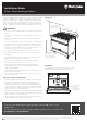


The freestanding type installation requires four screw-in feet to be
installed before it can be fitted in between cabinets, with cabinets
on one side or without adjacent cabinets. There is no clearance
requirement to adjacent side cabinets.
To ensure cooker stability, the anti-tilt brackets must be installed.
Four screw-in feet are supplied with the appliance and can be
found in the accessories pack in the oven. Select models are
supplied with a clip-on kick panel.
900mm minimum
755mm NOM
900mm NOM
600mm
both sides
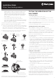
Installation of feet
• Freestanding appliances are supplied with four screw-in feet in
the internal accessory pack. The screw-in feet can be adjusted
by turning the lower half clockwise or anti-clockwise.
TIPS & INFORMATION
IMPORTANT
• WFE904 models are supplied with two silver feet and two black
feet, it is recommended to install the two silver feet at the front
of the appliance for the best aesthetics.
• If the appliance is a gas hob model, remove the burner cap
and burner crown. Store all items safely, away from the
installation area.
1. You MUST remove the oven door before commencing
installation.
Locking tab up at
normal position
Press the locking tab down for
removing the door.
Locking tab up at normal position.
Press the locking tab down for
removing the door.
Gently close the door until it comes to
a stop.Then lift the door off the hinge.
Locking tab up at normal position.
Press the locking tab down for
removing the door.
Gently close the door until it comes to
a stop.Then lift the door off the hinge.
2. Gently close the door until it comes to a stop.
Then lift the door off the hinge.
Installation Guide
90cm freestanding cookers
3. Tilt and carefully lay the appliance on its back to gain access to
the installation point for the screw in feet.
WARNING
CAUTION
• To avoid scratching the floor and the appliance itself, fold the
packaging carton board and place it underneath the appliance
as protection.
• The cooker MUST be laid on its back when installing the feet.
4. Install the four supplied feet via the four installation points.
Make sure that each foot is securely fastened.
Put the oven door handle
protection foam underneath the
laid down cooker to protect your
cooker when putting it upright
5. Adjust the height of the screw-in feet to make sure the hob
surface is 10mm above the bench when appliance is upright.
Bench height + 10mm minimum
6. Tilt the appliance upright by lifting the back of the hob and
pivoting it about the back two feet.
WARNING
WARNING
Heavy item! This step must be performed by two persons.
Levelling oven
Place a level in the oven as below making sure the level sits on the
front and rear forms. Adjust the feet accordingly to level the appliance.
Installing splashback
Fit splashback to rear of hob with three screws provided.
INSTALLATION OF ANTI-TILT
BRACKET
To ensure cooker stability, the anti-tilt brackets must be installed.
There are left and right engagement slots for the anti-tilt bracket
at the bottom rear of the appliance. The following steps must be
followed to ensure the correct installation of anti-tilt brackets and
the stability of the appliance.
Anti-tilt bracket engagement slots
WARNING
CAUTION
It is not recommended to push and pull the appliance on uneven
or rough surface. Use other means to manoeuvre the appliance if
necessary.
1. Carefully push the appliance into the cabinet cavity until the back
of the oven is flush against the back wall.
2. Use non-permanent methods to mark a line on the wall along the
top surface of the splashback. This line is used as a reference line
to locate the correct location of where the anti-tilt brackets need
to be installed.
3. After the reference line is marked, pull the appliance out of the
cabinet cavity to install the anti-tilt brackets.
Anti-tilt bracket installation
reference line
WARNING
WARNING
• Appropriate fasteners must be used to suit the type of wall on
which the anti-tilt brackets are installed.
• Freestanding unit must be pushed up against the wall on
installation. On gas units check that the gas hose, if used,
has not been kinked during installation.
4. The anti-tilt brackets must be secured to the rear wall of the cavity
with appropriate fasteners according to dimensions in diagram.
Install anti-tilt
brackets in
this orientation
as shown
(fasteners not
supplied)
C
L
425
Anti-tilt bracket
installation
reference line
725
370 370
Freestanding installation checklist
Connect services to the appliance prior to placing into cavity.
To locate appliance, slide into cavity ensuring the anti-tilt brackets
fully engaged with the rear left and right engagement slots.
The unit must be pushed against the wall on installation.
Re-install oven door, burner body, burner caps and trivets after the
appliance is placed in the cavity.
Gas only: check that the gas hose, if used, has not been kinked
during installation
FREESTANDING INSTALLATION
32