RPB+; Remote Power Boot Switch -- User's Guide WTI Part No.: 12651 Rev. B RPB+ Remote Power Boot Switch User's Guide 5 Sterling, Irvine, California 92618-2517 USA U.S. & Canada: (800) 854-7226 Phone: (949) 586-9950 Fax: (949) 583-9515 www.wti.com Table of Contents ● 1. Introduction ● 2. Unit Description ● ❍ 2.1. Front Panel ❍ 2.2. Back Panel 3. Installation ❍ 3.1. SetUp Switches ❍ 3.2. Control Port Connection ■ ❍ ● 3.3. Power Connection 4. Start-Up / Configuration ❍ ● 3.2.1.
RPB+; Remote Power Boot Switch -- User's Guide ● A. Specifications ● B. Customer Service List of Figures ● 1. Front Panel ● 2. Back Panel ● 3. RS-232 (Control Port) Interface Schematic ● 4. RPB+ Cable Connections ● 5. The Status Screen 1. Introduction Network equipment sometimes "locks-up", making it impossible to communicate. The RPB+ Remote Power Boot Switch can switch AC power on 5 individually controlled plugs, allowing attached equipment to reset (re-boot).
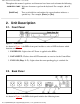
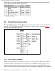
RPB+; Remote Power Boot Switch -- User's Guide Throughout this manual, typefaces and characters have been used to denote the following: COURIER FONT Indicates characters typed on the keyboard. For example, /S or /3 ON. [Bold Font] Text set in bold face and enclosed in square brackets indicates a specific key. For example, [Enter] or [Esc]. 2. Unit Description 2.1.
RPB+; Remote Power Boot Switch -- User's Guide 1. Switched AC Outlets (Plugs 1 - 5): For connection to up to five AC devices. Each outlet is capable of switching up to 15 Amps. The total for all five outlets must not exceed 15 Amps. 2. SetUp Switches (RATE): A bank of four DIP Switches which set the Control Port baud rate, select the Off Time duration, enable/disable the Password Option, and enable/disable the Read Only Mode. 3. RS232 (Control) Port: For connection to an external modem or local PC.
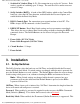
RPB+; Remote Power Boot Switch -- User's Guide allows the user to invoke On/Off/Boot commands, but prevents redefinition of parameters such as the Password and Power-Up Default. Switch Function Up Down 1 Control Port Baud Rate 2 Off Time 10 sec. 5 sec.* 3 Password Function Disable Enable* 4 Read Only Mode Enable Disable* 2400 bps 9600 bps* * = Factory Setting 3.2. Control Port Connection The male, DB9 connector (labeled "RS232") is used for connection to an external modem or local PC.
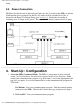
RPB+; Remote Power Boot Switch -- User's Guide string. 3.3. Power Connection The Power Switch located on the back panel must be "On" in order for the RPB+ to operate. Each time the unit is powered On, the five AC outlets will be switched On or Off, as dictated by the Power-Up Default String (see Section 4.1). Each outlet is capable of switching up to 15 Amps of AC power. The total for all 5 outlets cannot exceed 15 Amps. Figure 4: RPB+ Cable Connections 4. Start-Up / Configuration 1.
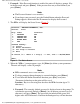
RPB+; Remote Power Boot Switch -- User's Guide 2. Password: If the Password function is enabled, the unit will display a prompt. Key in the Password and press [Enter]. If the password has not yet been defined, just press [Enter]. Note: ● The Password feature is case sensitive. ● If you forget your password, press the Default Button when the Password Prompt appears, then invoke the /P command to display the Password. 3. The RPB+ will display the Status Screen (Figure 5). Location: WESTERN TELEMATIC, INC.
RPB+; Remote Power Boot Switch -- User's Guide during password definition. c. Default (Power-Up Default): Allows the user to define default On/Off conditions for each switched plug as described in Section 4.1. Key in the desired Power-Up Defaults and press [Enter]. d. Echo Mode: When Echo Mode is enabled, commands sent to the RPB+ will be echoed back to your PC or terminal, allowing keyboard entries to be displayed by your communications program.
RPB+; Remote Power Boot Switch -- User's Guide Example 1: To set default On/Off conditions as follows: ON: Plugs 1 and 5 OFF: Plugs 2, 3, and 4 The Power-Up Default String would be defined as "10001". Example 2: To set default plug conditions as follows: ON: Plugs 3, 4, and 5 OFF: Plugs 1 and 2 The Power-Up Default String would be defined as "00111". 5. Operation The device connected to the Control Port must send ASCII characters at the same data rate as the RPB+.
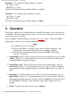
RPB+; Remote Power Boot Switch -- User's Guide 5. Enter Parameters: To define parameters, such as the Location I.D., Power-Up Default, and Plug Labels, type /P [Enter] and refer to Section 4, Step 4. 6. Set Plugs to Default: To set all plugs to the Power-Up Defaults, type /D [Enter]. Note that if the Default String includes missing or invalid characters, the /D command will not function. 7. Exit: To exit from command mode, type /X [Enter].
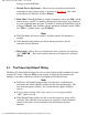
RPB+; Remote Power Boot Switch -- User's Guide 2 3 4 5 6 7 8 9 ❍ ❍ RXD TXD DTR GND (NC) RTS (NC) (NC) Data Input Data Output Ready Output Signal Ground Not Connected RTS Output Not Connected Not Connected Coding: Asynchronous. 7-8 bits, any parity Data Rate: 2400, 9600 bps (Switch Selectable) ● LEDs: Power ON, Control Input, Plug On (5) ● Temperature: 0° C to 30° C (operating) ● Power: ❍ 115 VAC Model: Internal 115 VAC 60 Hz (15 Amps Maximum Load).
RPB+; Remote Power Boot Switch -- User's Guide Irvine, California 92618 Toll Free (U.S. & Canada): 1-800-854-7226 Phone: 949-586-9950 Fax: 949-583-9514 EMail: service@wti.com FCC Statement This device complies with part 15 of the FCC rules. Operation is subject to the following two conditions: 1. This device may not cause harmful interference, and 2. This device must accept any interference received, including interference that may cause undesired operation.