
User`s guide

4-2
Hardware Installation
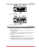
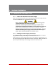
4.1.3. DC Powered Units
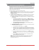
When connecting a DC Powered TSM Series or RSM Series unit to your DC Power
source, note that the DC terminal block is designed for connection to two separate
power sources. First remove the protective cover from the terminal block, attach the
wires from the -48 VDC power sources to the screw terminals, connect the ground line
to the labeled ground screw, tighten the screw terminals, making certain that the wires
are securely fastened, and then replace the protective cover.
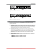
4.2. Connecting the Network Cable
The Network Port is an RJ45 Ethernet jack, for connection to a TCP/IP network.
Connect your 100Base-T cable to the Network Port. Note that the TSM/RSM includes a
default IPv4 protocol IP address (192.168.168.168) and a default IPv4 protocol subnet
mask (255.255.255.0.) When installing the TSM/RSM in a working network environment,
it is recommended to define network parameters as described in Section 5.9.
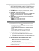
4.3. The Internal Modem Port
If you wish to use the TSM/RSM's internal modem (if present) in your application,
connect an RJ11 phone line to the Internal Modem port, located on the TSM/RSM
back panel. For information on Modem Port configuration, please refer to Section 5.8.
Note that an external modem can also be connected to the TSM/RSM serial ports as
described in Section 4.5, Appendix B and Appendix C.
Note: ModelsTSM-8-NMI,TSM-8DC-NMI,TSM-24-NMI,TSM-24DC-NMI,
TSM-40-NMIandTSM-40DC-NMIdonotincludeaninternalmodem.
-48V
-48V -48V00
0.1A
BUS A BUS B
Ground Screw
Figure 4.1: Terminal Block Assembly (TSM Series, DC Units Only)
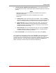
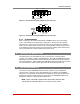
-48V 0.1A
0
-48V
A
-48V
B
GROUND
SCREW
Figure 4.2: Terminal Block Assembly (RSM Series, DC Units Only)