
User`s guide

2-10
Unit Description
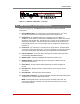
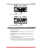
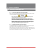
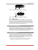
2.9. RSM-8R4-DCM Series - Front Panel Components
As shown in Figures 2.14 and 2.15, the front panel on RSM-8R4-DCM series units
includes the following components:
DEFButton(Default): Switches all plugs Off or sets plugs to default values as
described in Section 2.10.
RSTButton(Reset): Restarts the RSM-8R4-DCM as described in Section 2.10.
RDYIndicator: (Ready) Flashes to indicate that the unit is ready to receive
commands.
Ã
ACTIndicator(PortActivity): An LED indicator, which lights to indicate data
activity at the RSM-8R4-DCM Serial Ports.
SerialPorts: For connection to console ports on target devices. Standard RJ45
connectors configured as DCE ports. For more information on connecting devices
to the serial ports, please refer to Section 4.5 and Appendix B and Appendix C.
A 1
A 2 A 3 A 4
PHONE
LINE
DCD
ACT
RDY
DEF RST
SETUP PORT
2 1 3 4 5 6 7 8
SERIAL PORTS
Ethernet
ACT LINK
RSM-8R4
1
2
3
4
5
6
7
8
9
10
A 1
A 2 A 3 A 4
PHONE
LINE
DCD
ACT
RDY
DEF RST
SETUP PORT
2 1 3 4 5 6 7 8
SERIAL PORTS
Ethernet
ACT LINK
RSM-8R4
1
2
3
4
5
6
7
8
9
10
Figure 2.14: RSM-8R4-1-DCM - Front Panel
Figure 2.15: RSM-8R4-2-DCM - Back Panel