
User`s guide

2-4
Unit Description
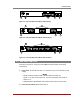
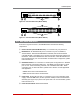
2.3. Front Panel (RSM Series)
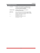
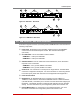
As shown in Figure 2.5, the RSM front panel includes the following components:
CLEAR: Can be used to restart the RSM operating system as described in
Section 2.10.
ON: Lights when AC Power is applied.
SET: Can be used to initialize the RSM to default parameters as described in
Section 2.10.
Ã
RDY: (Ready) Flashes to indicate unit is operational.
ACTIVITYLEDs: A series of LEDs, which light to indicate data activity at the
corresponding port.
• RSM-8 series units include 8 Activity LEDs
• RSM-16 series units include 16 Activity LEDs
CLEAR
SET
ON
RDY
CONNECTIONS
1
2 3
4
5 6
7 8
www.wti.com
RSM-8
Remote
Site Manager
1
2
3
4
5
Figure 2.5: Instrument Front Panel (Model RSM-8 Shown)