
User`s guide
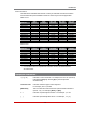


Table Of Contents
- Figure 2.1: VMR Series - Front Panel (Model VMR-16HD20-1 Shown)
- Figure 2.2: VMR Series - Back Panel (Model VMR-16HD20-1 Shown)
- Figure 2.3: NPS Series - Front Panel (Model NPS-16HD20-1 Shown)
- Figure 2.4: NPS Series - Back Panel (Model NPS-16HD20-1 Shown)
- Figure 5.1: Boot Priority Example 1
- Figure 5.2: Boot Priority Example 2
- Figure 9.1: The Help Menu (Administrator Mode; Text Interface - VMR Shown)
- Figure 14.1: Web Access Parameters (Text Interface Only)
- Figure B.1: RS232 SetUp Port Interface
- 1. Introduction
- 2. Unit Description
- 3. Getting Started
- 4. Hardware Installation
- 5. Basic Configuration
- 5.1. Communicating with the VMR or NPS Unit
- 5.2. Configuration Menus
- 5.3. Defining System Parameters
- 5.4. User Accounts
- 5.5. Managing User Accounts
- 5.6. The Plug Group Directory
- 5.7. Defining Plug Parameters
- 5.8. Serial Port Configuration
- 5.9. Network Configuration
- 5.10. Save User Selected Parameters
- 6. Reboot Options
- 7. Alarm Configuration
- 8. The Status Screens
- 9. Operation
- 10. SSH Encryption
- 11. Syslog Messages
- 12. SNMP Traps
- 13. Operation via SNMP
- 14. Setting Up SSL Encryption
- 15. Saving and Restoring Configuration Parameters
- 16. Upgrading VMR/NPS Firmware
- 17. Command Reference Guide
- Appendix A. Specifications
- Appendix B. Interface Descriptions
- Appendix C. Customer Service
- Index
3-1
3. Getting Started
This Quick Start Guide describes a simplified installation procedure for the VMR and
NPS series hardware, which will allow you to communicate with the unit in order to
demonstrate basic features and check for proper operation.
Note that this Quick Start Guide does not provide a detailed description of unit
configuration, or discuss advanced operating features in detail. In order to take full
advantage of the features provided by this unit, it is recommended that you should refer
to the remainder of this User’s Guide.
3.1. Installing the VMR Hardware
3.1.1. Apply Power to the VMR or NPS
Refer to power rating nameplate on the VMR or NPS unit, and then connect the unit to
an appropriate power source. Note that some VMR/NPS models feature two separate
AC inputs and two separate power branches, while others feature a single power inlet.
Connect power cable(s) to the Power Inlet(s), install the cable keeper(s) (as described
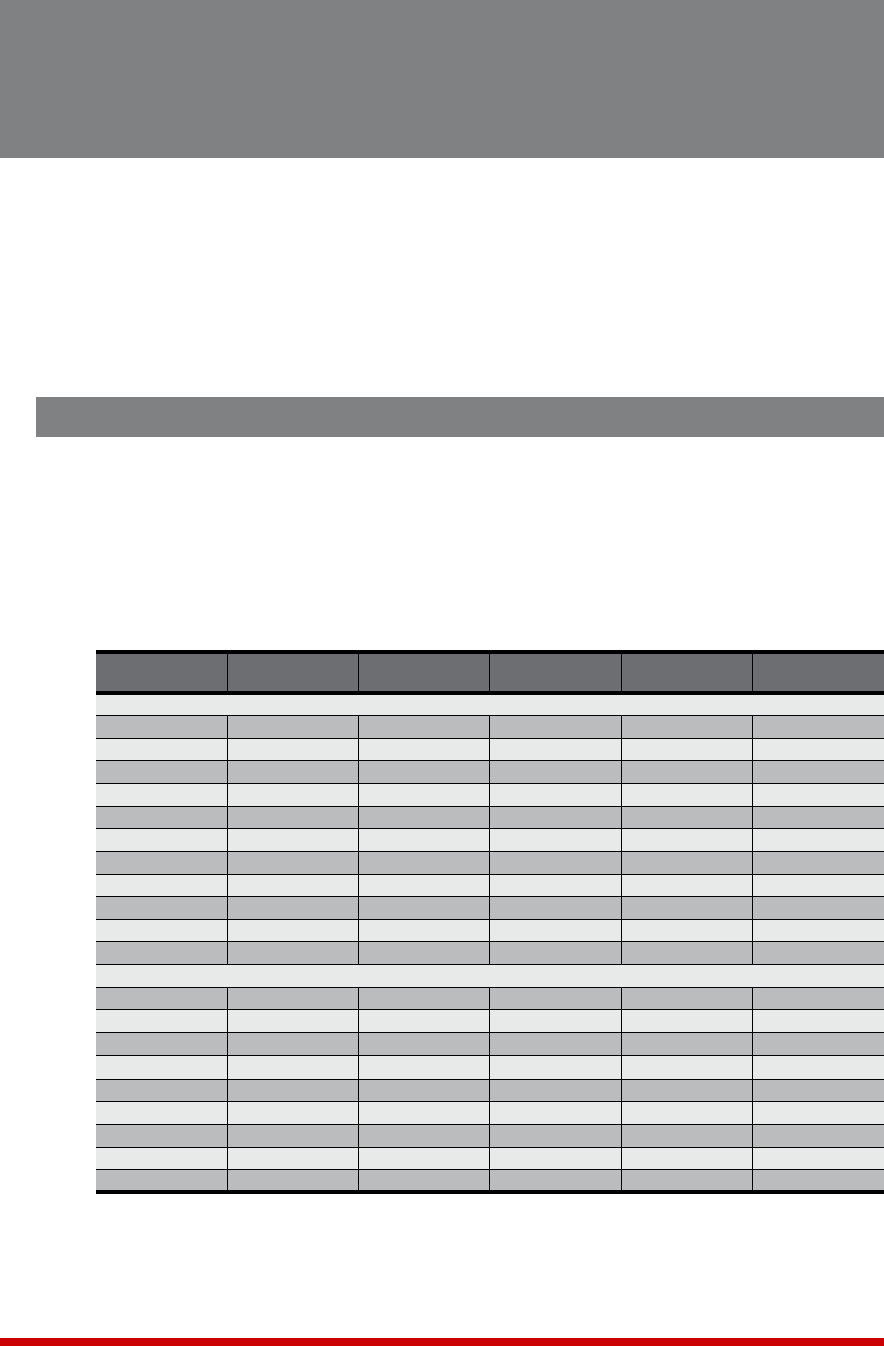
in Section 4.1.1), then connect the cables to an appropriate power supply. Refer to the
table below for information concerning power requirements and maximum load.
Model No.
Input
Feeds
Input
Voltage
Max. Load
per Outlet
Max. Load
per Input
Max. Load
per Unit
VMR Series
VMR-4HS15-1 1 ea, 15 Amp 100 to 120 VAC 12 Amps 12 Amps* 12 Amps*
VMR-4HS15-2 1 ea, 15 Amp 100 to 240 VAC 10 Amps 12 Amps* 12 Amps*
VMR-8HS20-1 1 ea, 20 Amp 100 to 120 VAC 15 Amps 16 Amps* 16 Amps*
VMR-8HS20-2 1 ea, 20 Amp 100 to 240 VAC 10 Amps 16 Amps* 16 Amps*
VMR-8HS16-3 1 ea, 16 Amp 200 to 240 VAC 10 Amps 16 Amps 16 Amps
VMR-8HD20-1 2 ea, 20 Amp 100 to 120 VAC 12 Amps 16 Amps* 32 Amps*
VMR-8HD20-2 2 ea, 20 Amp 100 to 240 VAC 10 Amps 16 Amps * 32 Amps*
VMR-8HD16-3 2 ea, 16 Amp 200 to 240 VAC 10 Amps 16 Amps 32 Amps
VMR-16HD20-1 2 ea, 20 Amp 100 to 120 VAC 12 Amps 16 Amps * 32 Amps*
VMR-16HD20-2 2 ea, 20 Amp 100 to 240 VAC 10 Amps 16 Amps* 32 Amps*
VMR-16HD16-3 2 ea, 16 Amp 200 to 240 VAC 10 Amps 16 Amps 32 Amps
NPSSeries
NPS-8HS20-1 1 ea, 20 Amp 100 to 120 VAC 15 Amps 16 Amps* 16 Amps*
NPS-8HS20-2 1 ea, 20 Amp 100 to 240 VAC 10 Amps 16 Amps* 16 Amps*
NPS-8HS16-3 1 ea, 16 Amp 200 to 240 VAC 10 Amps 16 Amps 16 Amps
NPS-8HD20-1 2 ea, 20 Amp 100 to 120 VAC 15 Amps 16 Amps* 32 Amps*
NPS-8HD20-2 2 ea, 20 Amp 100 to 240 VAC 10 Amps 16 Amps* 32 Amps*
NPS-8HD16-3 2 ea, 16 Amp 200 to 240 VAC 10 Amps 16 Amps 32 Amps
NPS-16HD20-1 2 ea, 20 Amp 100 to 120 VAC 15 Amps 16 Amps* 32 Amps*
NPS-16HD20-2 2 ea, 20 Amp 100 to 240 VAC 10 Amps 16 Amps* 32 Amps*
NPS-16HD16-3 2 ea, 16 Amp 200 to 240 VAC 10 Amps 16 Amps 32 Amps
* In accordance with UL requirements, this value has been de-rated to 80%.
Note: To determine the exact model number for your VMR or NPS unit, either
refer to the nameplate on the back of the unit, or access command mode as
described in Section 5.1 and then type /J * and press [Enter].