
User`s guide

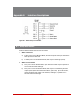


Table Of Contents
- Figure 2.1: VMR Series - Front Panel (Model VMR-16HD20-1 Shown)
- Figure 2.2: VMR Series - Back Panel (Model VMR-16HD20-1 Shown)
- Figure 2.3: NPS Series - Front Panel (Model NPS-16HD20-1 Shown)
- Figure 2.4: NPS Series - Back Panel (Model NPS-16HD20-1 Shown)
- Figure 5.1: Boot Priority Example 1
- Figure 5.2: Boot Priority Example 2
- Figure 9.1: The Help Menu (Administrator Mode; Text Interface - VMR Shown)
- Figure 14.1: Web Access Parameters (Text Interface Only)
- Figure B.1: RS232 SetUp Port Interface
- 1. Introduction
- 2. Unit Description
- 3. Getting Started
- 4. Hardware Installation
- 5. Basic Configuration
- 5.1. Communicating with the VMR or NPS Unit
- 5.2. Configuration Menus
- 5.3. Defining System Parameters
- 5.4. User Accounts
- 5.5. Managing User Accounts
- 5.6. The Plug Group Directory
- 5.7. Defining Plug Parameters
- 5.8. Serial Port Configuration
- 5.9. Network Configuration
- 5.10. Save User Selected Parameters
- 6. Reboot Options
- 7. Alarm Configuration
- 8. The Status Screens
- 9. Operation
- 10. SSH Encryption
- 11. Syslog Messages
- 12. SNMP Traps
- 13. Operation via SNMP
- 14. Setting Up SSL Encryption
- 15. Saving and Restoring Configuration Parameters
- 16. Upgrading VMR/NPS Firmware
- 17. Command Reference Guide
- Appendix A. Specifications
- Appendix B. Interface Descriptions
- Appendix C. Customer Service
- Index

Index-2
Index
Command Prompt 5-15
Command Reference Guide 17-1 to 17-10
Command Set
Text Interface 17-3 to 17-10
Common Name 14-2
Communication 5-1 to 5-3
Configuration 5-1 to 5-47
Menus 5-4
Restore Previous 5-47, 15-3
Restoring 15-2
Saving 15-1, 17-8
Via SNMP 13-2 to 13-3
Confirmation Prompt 9-5, 5-15
Connecting Ports 17-8
Consecutive Failures
Ping-No-Answer Reboot 6-2
Console Port 2-1, 2-3
Administrator 5-27
Configuration 5-27 to 5-30, 17-9
Interface Apx-2
SuperUser 5-27
Supervisor Mode 5-27
Copyrights Apx-4
Copy to All Triggers
Circuit Breaker Open Alarm 7-9
Invalid Access Lockout Alarm 7-14
Lost Voltage Alarm 7-10
Over Current Alarms 7-3
Over Temperature Alarms 7-7
Ping-No-Answer Alarm 7-12
Country 14-2
Create CSR 14-3
CRT Server Key
Upload 14-4
Current Capacity 3-1
Current History Screen 8-6 to 8-7
Current Metering
Text Interface 17-4
Current Metering Log 5-10, 5-20
LDAP Group 5-40
Current Metering Status Screen 8-5 to 8-6
Current/Power Metering
TACACS 5-43
Current Usage Indicators 2-1
Customer Service Apx-3
D
Date 5-7
Day Access
Scheduled Reboots 6-5
Debug
LDAP Parameters 5-40
RADIUS 5-44
Default All Plugs 2-5
Default Button 2-1, 2-3, 2-5
Defaulting Plugs
Text Interface 17-7
Default Parameters 2-5
Default User Access 5-42
Delete
LDAP Groups 5-41
Ping-No-Answer Reboot 6-4
Plug Groups 5-23
Scheduled Reboot 6-6
User Accounts 5-21
Via SNMP 13-3
Deny List 5-34
DHCP 5-31
Dialback Security 5-6, 5-13 to 5-14
Dictionary Support
RADIUS 5-45
Domain
Energywise Configuration 5-7
Domain Name
Email Parameters 5-46
Domain Name Server 5-36
Ping Test 5-36
DSA Client 10-1
DTR Output 5-28
SetUp Port 5-28
E
Email Address
SSL Certificate 14-2
Email Message
Circuit Breaker Open Alarm 7-9
Invalid Access Lockout Alarm 7-14
Lost Voltage Alarm 7-10
Over Current Alarms 7-3
Over Temperature Alarms 7-7
Ping-No-Answer Alarm 7-12
Plug Current Alarm 7-17
Power Cycle Alarm 7-15
Email Parameters 5-46
Authentication Type 5-46
Domain 5-46
From Address 5-46
From Name 5-46
Password 5-46
Port Number 5-46
Send Test Email 5-46
SMTP Server 5-46
To Address 5-46
User Name 5-46
Enable
Energywise Configuration 5-7
Encryption 14-1 to 14-3