
User`s guide

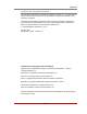


Table Of Contents
- Figure 2.1: VMR Series - Front Panel (Model VMR-16HD20-1 Shown)
- Figure 2.2: VMR Series - Back Panel (Model VMR-16HD20-1 Shown)
- Figure 2.3: NPS Series - Front Panel (Model NPS-16HD20-1 Shown)
- Figure 2.4: NPS Series - Back Panel (Model NPS-16HD20-1 Shown)
- Figure 5.1: Boot Priority Example 1
- Figure 5.2: Boot Priority Example 2
- Figure 9.1: The Help Menu (Administrator Mode; Text Interface - VMR Shown)
- Figure 14.1: Web Access Parameters (Text Interface Only)
- Figure B.1: RS232 SetUp Port Interface
- 1. Introduction
- 2. Unit Description
- 3. Getting Started
- 4. Hardware Installation
- 5. Basic Configuration
- 5.1. Communicating with the VMR or NPS Unit
- 5.2. Configuration Menus
- 5.3. Defining System Parameters
- 5.4. User Accounts
- 5.5. Managing User Accounts
- 5.6. The Plug Group Directory
- 5.7. Defining Plug Parameters
- 5.8. Serial Port Configuration
- 5.9. Network Configuration
- 5.10. Save User Selected Parameters
- 6. Reboot Options
- 7. Alarm Configuration
- 8. The Status Screens
- 9. Operation
- 10. SSH Encryption
- 11. Syslog Messages
- 12. SNMP Traps
- 13. Operation via SNMP
- 14. Setting Up SSL Encryption
- 15. Saving and Restoring Configuration Parameters
- 16. Upgrading VMR/NPS Firmware
- 17. Command Reference Guide
- Appendix A. Specifications
- Appendix B. Interface Descriptions
- Appendix C. Customer Service
- Index
Apx-2
Appendix B. Interface Descriptions
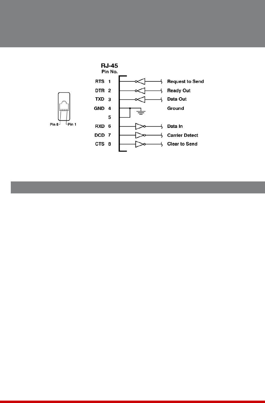
B.1. SetUp Port (RS232)
DCD and DTR hardware lines function as follows:
1. Whenconnected:
a) If either port is set for Modem Mode, the DTR output at either port reflects the
DCD input at the other end.
b) If neither port is set for Modem Mode, DTR output is held high (active).
2. Whennotconnected:
a) If the port is set for Modem Mode, upon disconnect DTR output is pulsed for
0.5 seconds and then held high.
b) If the port is not set for Modem Mode, DTR output is controlled by the DTR
Output option (Serial Port Parameters Menu, Option 23). Upon disconnect,
Option 23 allows DTR output to be held low, held high, or pulsed for 0.5
seconds and then held high.
Figure B.1: RS232 SetUp Port Interface