
User`s guide
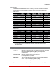


Table Of Contents
- Figure 2.1: VMR Series - Front Panel (Model VMR-16HD20-1 Shown)
- Figure 2.2: VMR Series - Back Panel (Model VMR-16HD20-1 Shown)
- Figure 2.3: NPS Series - Front Panel (Model NPS-16HD20-1 Shown)
- Figure 2.4: NPS Series - Back Panel (Model NPS-16HD20-1 Shown)
- Figure 5.1: Boot Priority Example 1
- Figure 5.2: Boot Priority Example 2
- Figure 9.1: The Help Menu (Administrator Mode; Text Interface - VMR Shown)
- Figure 14.1: Web Access Parameters (Text Interface Only)
- Figure B.1: RS232 SetUp Port Interface
- 1. Introduction
- 2. Unit Description
- 3. Getting Started
- 4. Hardware Installation
- 5. Basic Configuration
- 5.1. Communicating with the VMR or NPS Unit
- 5.2. Configuration Menus
- 5.3. Defining System Parameters
- 5.4. User Accounts
- 5.5. Managing User Accounts
- 5.6. The Plug Group Directory
- 5.7. Defining Plug Parameters
- 5.8. Serial Port Configuration
- 5.9. Network Configuration
- 5.10. Save User Selected Parameters
- 6. Reboot Options
- 7. Alarm Configuration
- 8. The Status Screens
- 9. Operation
- 10. SSH Encryption
- 11. Syslog Messages
- 12. SNMP Traps
- 13. Operation via SNMP
- 14. Setting Up SSL Encryption
- 15. Saving and Restoring Configuration Parameters
- 16. Upgrading VMR/NPS Firmware
- 17. Command Reference Guide
- Appendix A. Specifications
- Appendix B. Interface Descriptions
- Appendix C. Customer Service
- Index

2-3
Unit Description
2.3. NPS Series - Front Panel
As shown in Figure 2.3, the NPS Series Front Panel includes the following components:
1. SetUpPort: An RJ45 RS232 serial port (DCE configuration) used for connection to
a local terminal or external modem, as described in Section 4.3.2. For a description
of the Setup Port interface, please refer to Appendix B.1.
2. "ON"Indicator: An LED which lights when power is applied to the VMR unit.
3. "RDY"Indicator: (Ready) Flashes if unit is ready to receive commands.
4. DefaultButton: Manually toggles outlets On/Off or resets unit to factory default
parameters as described in Section 2.5.
5. ResetButton: Reboots and/or resets the NPS to factory defaults as described in
Section 2.5.
Note: All Front Panel Button functions can also be disabled via the System
Parameters menu, as described in Section 5.3.
6. OutputStatusIndicators: LEDs light when corresponding outlet is switched On.
7. BranchACircuitBreakers: Two circuit breakers, which protect Branch A. One
circuit breaker protects outlets A1 through A4, and the other circuit breaker protects
outlets A5 through A8. Circuit Breakers on NPS models are rated as follows:
• NPS-**-1SeriesandNPS-**-2Series: 20 Amps
• NPS--3Series: 16 Amps
8. BranchBCircuitBreakers: Same as Item 7 above, except circuit breakers protect
outlets on Branch B. (Not present on NPS-8HS series units.)
www.wti.com
NPS-16
Network Power Switch
SETUP PORT
DEFAULT
OUTPUT STATUS
RESET
ON RDY
A1 A2 A3 A4 A5 A6 A7 A8
B1 B2 B3 B4 B5 B6 B7 B8
A1 - A4 A5 - A8
B5 - B8B1 - B4
1 2 3 4
5
6 8
7
Figure 2.3: NPS Series - Front Panel (Model NPS-16HD20-1 Shown)