
User`s guide


Table Of Contents
- Figure 2.1: VMR Series - Front Panel (Model VMR-16HD20-1 Shown)
- Figure 2.2: VMR Series - Back Panel (Model VMR-16HD20-1 Shown)
- Figure 2.3: NPS Series - Front Panel (Model NPS-16HD20-1 Shown)
- Figure 2.4: NPS Series - Back Panel (Model NPS-16HD20-1 Shown)
- Figure 5.1: Boot Priority Example 1
- Figure 5.2: Boot Priority Example 2
- Figure 9.1: The Help Menu (Administrator Mode; Text Interface - VMR Shown)
- Figure 14.1: Web Access Parameters (Text Interface Only)
- Figure B.1: RS232 SetUp Port Interface
- 1. Introduction
- 2. Unit Description
- 3. Getting Started
- 4. Hardware Installation
- 5. Basic Configuration
- 5.1. Communicating with the VMR or NPS Unit
- 5.2. Configuration Menus
- 5.3. Defining System Parameters
- 5.4. User Accounts
- 5.5. Managing User Accounts
- 5.6. The Plug Group Directory
- 5.7. Defining Plug Parameters
- 5.8. Serial Port Configuration
- 5.9. Network Configuration
- 5.10. Save User Selected Parameters
- 6. Reboot Options
- 7. Alarm Configuration
- 8. The Status Screens
- 9. Operation
- 10. SSH Encryption
- 11. Syslog Messages
- 12. SNMP Traps
- 13. Operation via SNMP
- 14. Setting Up SSL Encryption
- 15. Saving and Restoring Configuration Parameters
- 16. Upgrading VMR/NPS Firmware
- 17. Command Reference Guide
- Appendix A. Specifications
- Appendix B. Interface Descriptions
- Appendix C. Customer Service
- Index
2-2
Unit Description
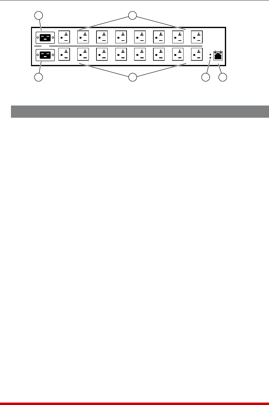
2.2. VMR Series - Back Panel
As shown in Figure 2.2, the VMR Series Back Panel includes the following components:
1. PowerCircuitA-PowerInlet: An IEC320-C20 AC inlet which supplies power to
VMR control functions and Circuit “A” outlets. Also includes cable keeper
(not shown.)
Note: VMR-4HS15 and VMR-8HS20 series units feature a single Power Inlet.
2. PowerCircuitB-PowerInlet: An IEC320-C20 AC inlet which supplies power to
VMR control functions and Circuit “B” outlets. Also includes cable keeper
(not shown.) (Not present on VMR-4HS15 and VMR-8HS20 series units.)
3. PowerCircuitA-SwitchedOutlets: AC Outlets that can be switched On, Off,
rebooted or set to default state in response to user commands:
• VMR-4HS15-1: Four (4) each, NEMA 5-20R Outlets.
• VMR-4HS15-2: Four (4) each, IEC320-C13 Outlets.
• VMR-8HS20-1: Eight (8) each, NEMA 5-20R Outlets.
• VMR-8HS20-2: Eight (8) each, IEC320-C13 Outlets.
• VMR-8HD20-1: Four (4) each, NEMA 5-20R Outlets.
• VMR-8HD20-2: Four (4) each, IEC320-C13 Outlets.
• VMR-16HD20-1: Eight (8) each, NEMA 5-20R Outlets.
• VMR-16HD20-2: Eight (8) each, IEC320-C13 Outlets.
4. PowerCircuitB-SwitchedOutlets: Same as Item 3 above. (Not present on
VMR-4HS15 and VMR-8HS20 series units.)
5. AlarmIndicatorLights: Two LEDs which light when an alarm condition is detected
at the corresponding power circuit. Note that VMR-4HS15 and VMR-8HS20 series
units only include one power circuit and one Alarm Indicator Light. For information
on Alarm Configuration, please refer to Section 7.
6. NetworkPort: An RJ45 Ethernet port for connection to your 100Base-T, TCP/IP
network. Note that the VMR features a default IP address (192.168.168.168). This
allows you to connect to the unit without first assigning an IP address. Note that the
Network Port also includes two, small LED indicators for Link and Data Activity. For
more information on Network Port configuration, please refer to Section 5.9.
A-1
BUS A
BUS B
A-2
A-3 A-4 A-5
A-6
A-7 A-8
B-1 B-2 B-3 B-4 B-5
B-6 B-7
B-8
10/100 BaseT
ACT
A
B
ALARM
LINK
1
3
2
4
5
6
Figure 2.2: VMR Series - Back Panel (Model VMR-16HD20-1 Shown)