OPERATORS MANUAL . MARINE DIESEL ENGINES 308· THREE 30C·THREE 208-TWO PUBLICATION N0.36906 REVISION FIVE JANUARY 2011 WESTERBEKE CORPORATION • 150 JOHN HANCOCK ROAD MYLES STANDISH INDUSTRIAL PARK• TAUNTON MA 02780 WEBSITE: WWW. WESTERBEKE.COM ...........__. NAMIA ~,.,., Member National Marine Manufacturers Association .
A wARNING·· Exhaust gasses contain Carbon Monoxide, an odorless ani/ colorless gas. Carbon Monoxide is poisonous and can cause unconsciousness and death. Symptoms of Carbon Monoxide exposure can include: • Throbbing in Temples •Dizziness • Muscular Twitching •Nausea •Headache • Vomiting • Weakness and Sleepiness •Inability to Think Coherently IF. YOU OR ANYONE ELSE EXPERIENCE ANY OF THESE SYMPTOMS, GET OUT INTO THE FRESH AIR IMMEDIATELY. If symptoms persist, seek medical attention.
SAFETY INSTRUCTIONS INTRODUCTION PREVENT BURNS - FIRE Read this safety· manual carefully. Most accidents are caused by failure to follow fundamental rules and precautions. Know when dangerous conditions exist and take the necessary precautions to protect yourself, your personnel, and your machinery. The following safety instructions are in compliance with the American Boat and Yacht Council (ABYC) standards.
SAFETY INSTRUCTIONS ACCIDENTAL STARTING TOXIC EXHAUST GASES A WARNING: Accidental starting can cause injury A WARNING: Carbon monoxide (CO) is a deadly gas! or death! • • • Disconnect the battery cables before servicing the engine/ generator. Remove the negative lead first and reconnect it last. Make certain all personnel are clear of the engine before starting. Make certain all covers, guards, and hatches are reinstalled before starting the engine.
SAFETY INSTRUCTIONS • • • • ABYC, NFPA AND USCG PUBLICATIONS FOR INSTALLING DIESEL ENGINES Do not wear loose clothing or jewelry when servicing equipment; tie back long hair and avoid wearing loose jackets, shirts, sleeves, rings, necklaces or bracelets that could be caught in moving parts. Read the following ABYC, NFPA and USCG publications for safety codes and standards. Follow their recommendations when installing your engine.
INSTALLATION When installing WESTERBEKE engines and generators it is important that strict attention be paid to the following information: CODES. AND REGULATIONS Strict federal regulations, ABYC guidelines, and safety codes must be complied with when installing engines and generators in a marine environment. SIPHON-BREAK For installations where the exhaust manifold/water injected.
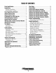
TABLE OF CONTENTS Parts Identification ................................................2 lntroduction .............................................................3 Glow Plugs .........................................................28 Starter Motor .....................................................29 Engine Wiring Diagram (#39144) ...................... 30 Engine Wiring Schematic (#39144) ................... 31 Admirals Panel Wiring Diagram (#36844) .........
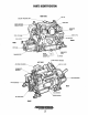
PARTS IDENTIFICATION RIGHT SIDE Oil Fill COOlANT PRESSURE CAP •SIDE Oil Fill FRONT REAR BlOCK COOlANT DRAIN PlUG 'RAW WATER PUMP Oil FilTER LEFT SIDE AIR INTAKE SilENCER ; NIT 1.0.
INTRODUCTION PRODUCT SOFTWARE This WESTERBEKE Diesel Engine is a product of WESTERBEKE's long years of experience and advanced technology. We take great pride in the superior durability and dependable performance of our engines and generators. Thank you for selecting WESTERBEKE. Product software, (tech data, parts lists, manuals, brochures and catalogs), provided from sources other than WESTERBEKE are not within WESTERBEKE's control.
INTRODUCTION SERIAL NUMBER LOCATION ORDERING PARTS The engine's model number and serial number are located on a nameplate mounted on the side of the engine's manifold. The engine's serial number is stamped into the engine block on the flat surface directly above the injection pump. Take the time to enter this information on the illustration of the nameplate shown below, as this will provide a quick reference when seeking technical information and/or ordering parts.
DIESEL FUEL, ENGINE OIL AND ENGINE COOLANT DIESEL FUEL ENGINE COOLANT USE A DIESEL FUEL WITH A CETANE RATING OF #45 OR HIGHER. (No. 2-D (SAE J313) diesel fuel according to ASTM D975). 'WESTERBEKE recommends a mixture of 50% antifreeze and 50% distilled water. Distilled water is free from the chemicals that can cmrode internal engine surfaces. The antifreeze performs double duty.
ADMIRAL CONTROL PANEL DESCRIPTION When the engine is shut down with the key switch turned off, the water temperature gauge will continue to register the last temperature reading indicated by the gauge before electrical power was turned off. The oil pressure gauge will fall to zero when the key switch is turned off. The temperature gauge will once again register the engine's true temperature when electrical power is restored to the gauge.
CAPTAIN CONTROL PANEL DESCRIPTION The panel also includes an a1ann buzzer for low OIL PRESSURE or high COOLANT TEMPERATURE. The RPM gauge is illuminated when the KEY switch is turned on and remains illuminated while the engine is in operation. This manually-operated control panel is equipped with a KEY switch, an RPM gauge, PREHEAT and START buttons, an INSTRUMENT TEST button and three indicator lamps, one for ALTERNKfOR DISCHARGE, one for low OIL PRESSURE, and one for high ENGINE COOLANT 1EMPERATURE.
PREPARATIONS FOR INITIAL START-UP NOTE: If the engine has not yet been filled with coolant, PRESTART INSPECTION refer to the COOUNG SYSTEM section of this manual. Before starting your engine for the first time or after a prolonged layoff, check the following items: 0 Visually examine the engine. Look for loose or missing parts, disconnected wires, and unattached hoses. Check the threaded connections and engine attachments. 0 Check the engine oil level.
STARTING/STOPPING PROCEDURE CHECK LIST FAILURE TO START Follow this check list each day before sta1ting your engine. If the engine fails to start when the start button is pressed for 5 seconds, wait for at least 30 seconds and repeatthe starting procedure. Make certain the transmission control is in the neutral position. 0 Visually inspect the engine for fuel, oil, or water leaks. D Check the oil level (dipstick). D Check the coolant level in the coolant recovery tank.
ENGINE BREAK-IN PROCEDURE DESCRIPTION 3. While using the vessel, run the engine at various engine speeds for the first 25 hours. Avoid prolonged periods of idling. 4. Avoid rapid acceleration, especially with a cold engine. Although your engine has experienced a minimum of one hour of test operations at the factory to make sure accurate assembly procedures were followed and that the engine operated properly, a break-in time is required.
WARNING LIGHTS, ALARMS &CIRCUIT BREAKER ALTERNATOR WARNINGS COOLANT TEMPERATURE SWITCH The Captain Control Panel indicates alternator low discharge with a red warning light. The Admiral Control Panel uses a voltmeter to monitor the performance of the alternator. A coolant temperature switch is located on the thermostat housing. This switch will activate a continuous alarmifthe coolant's operating temperature reaches approximately :?l0°f. (99°C).
MAINTENANCE SCHEDULE In order to use this Maintenance Schedule, it will be necessary to log your engine hours. Use your engine hourmeter or record your engine hours by rmming time. NOTE: Many of the following maintenance procedures are simple but others are more difficult and may require the expert knowledge of a service mechanic. SCHEDULED MAINTENANCE CHECK EACH DAY A WARNING: Never attempt to perform any service while the engine is running.
MAINTENANCE SCHEDULE NOTE: Use the engine hourmeter gauge to log your engine hours or record your engine hours by running time. SCHEDULED MAINTENANCE CHECK EACH DAY HOURS OF OPERATION 50 100 250 500 MAINTENANCE DESCRIPTION 750 1000 1250 D Raw Water Pump Remove the pump from the engine. Disassemble and inspect all components, replacing all worn components as needed. Inspect the drive gear slot for wear. Replace drive gear as needed. At 750 operating hours, disassemble and inspect for overhaul.
FUEL SYSTEM ENGINE FUEL FILTER DIESEL FUEL Periodically check the fuel connections and the bowl for leakage. Replace the filter element after the first 50 hours then follow the MAINTENANCE SCHEDULE. USE A DIESEL FUEL WITH A CETANE RATING OF #45 OR HIGHER. (No. 2-0 (SAE J313) diesel fuel according to ASTM 0975). Changing/cleaning the filter element FUEL FILTERS 1. Shut off the fuel supply.
ENGINE COOLING SYSTEM DESCRIPTION Westcrbeke marine diesel gen.erators are designed and equipped for fresh water cooling. Heat produced in the engine by combustion and friction is transferred to fresh water coolant which circulates throughout the engine. This circulating fresh water coolant cools the engine block and its internal nmving parts. The heat is transferred externally from the fresh water coolant to raw water by means of a heat exchanger; similar in function to an automotive radiator.
COOLING SYSTEM FRESH WATER COOLING CIRCUIT Fresh water coolant is pumped through the engine by a circulating pump, absorbing heat from the engine. The coolant then passes through the thermostat into the manifold, to the heat exchanger where it is cooled and returned to the engine block via the suction side of the circulating pump.
COOLING SYSTEM THERMOSTAT A thermostat, located near the manifold at the front of the engine, controls the coolant temperature as the coolant continuously flows through the closed cooling circuit. When the engine is first started, the closed thermostat prevents coolant from flowing (some coolant is by-passed through a hole in the thennostat to prevent the exhaust manifold from overheating). As the engine wanns up, the thermostat gradually opens.
COOLING SYSTEM RAW WATER PUMP (EARLY MODELS) RAW WATER PUMP The raw water pump is a,self-priming; rotary pump with a non-ferrous housing and a Neoprene impeller. The impeller has flexible blades which wipe against a curved cam plate within the impeller housing, producing the pumping action. On no account should this pump be run dry. There should always be a spare impeller and impeller cover gasket aboard (an impeller kit).
REPAIR PARTS ARE AVAILABlE FROM YOUR WESTERBEKE DEALER NOTE THE PUMP-flEPAIR KIT (49000) INCLUDES ALL THE LISTED COMPONENTS EXCEPT ITEMS 1 AND 7._THE KiT ALSO INCLUDES A PUMP MOUNTING GASKET. KEY NO. PART NUMBER AND PART NAME 1 2 3 4 5 6 7 8 48080 49172 49170 48500 34458 49171 302575 48253 34463 48359 33041 33037 46662 48254 49169 34464 . 33045 33044 · 49000 37431 9 10 11 12 13 ASSEMBLED VIEW 14' 15 16 17 18 ..... ~~ ~(I) RAW WATER PUMP SHAFT IMPELLER COVER IMflELI:.
COOLING SYSTEM Zinc Anode #011885 If the zinc anodes need replacement, hold the hex boss into which the zinc anode is threaded with a wrench while loosening the anode with another wrench. This prevents the hex boss from possibly tearing off the exchanger shell. After removing the Zinc, note the condition of it. If the zinc is in poor condition, there are probably· a lot of zinc flakes within the exchanger. Remove the end of the heat exchanger and clean the inside of all zinc debris.
ENGINE LUBRICATING OIL 2. Replacing the Oil Filter. When removing the used oil filter, you may find it helpful and cleaner to punch a hole . in the upper and lower portion of the old filter to drain the oil from it into a container before removing it. This helps to lessen spillage. A small style automotive filter wrench should be helpful in removing the old oil filter.
REMOTE OIL FILTER (OPTIONAL) PN# 040078 INSTALLATION This popular accessory is used to relocate the engine's oil filter from the engine to a more convenient location such as an engine room bulkhead. NOTE: Westerbeke is not responsible for engine failure due to incorrect installation of the Remote Oil Filter. . A CAUTION: It is vital to install the oil lines NOTE: Refer to ENGINE OIL CHANGE in this manual for instructions on removing the oil filter. correctly.
DOMESTIC HOT WATER TANK CONNECTIONS DESCRIPTION PREVIOUS MODEL ENGINES Both the two and three cylinder models are equipped with connections to send engine coolant to a domestic water heater. If the owner/operator wishes to connect a water heater, remove the bypass hose and connect a water heater as described in the instructions presented below . REMOVE THE BY-PASS HOSE HEATER BELOW ENGINE .
DOMESTIC HOT WATER TANK CONNECTIONS HOT WATER HEATER ABOVE THE ENGINE If any portion of the heating circuit rises above the engine's own pressure cap, the a pressurized (aluminum) remote expansion tank must be installed in the circuit to become the highest point. The remote expansion tanks part number is 24177. Tee the remote expansion tank into the heater circuit at the heater connection, choosing the higher of the two for the return.
TACHOMETER TACHOMETER/HOUR METER NOTE: Current model tachometers use a coarse adjustment dial to set the tachometer to the crankshaft pulley rpms. The calibrating screw is then used for fine tuning. The tachometer/hour meter used in propulsion engine instrument panels contain two separate electrical circuits with a common ground. One circuit operates the hour meter and the other the tachometer.
ALTERNATORS TESTING/TROUBLESHOOTING CASE GROUND 50 AMP TYPICAL ALTERNATOR VOLTAGE REGULATOR The integral voltage regulator is an electronic switching device which senses the system voltage level and switches the voltage applied to the field in order to maintain a proper system voltage. The regulator design utilizes all-silicon semi conductors and thick~film assembly techniques.
ALTERNATORS TESTING/TROUBLESHOOTING TESTING THE ALTERNATOR A CAUTION: Before starting the engine make certain that everyone is clear of moving parts! Keep away from sheaves and belts during test procedures. 1. Start the engine. 2. After the engine has run for a few minutes, measure the starting battery voltage at the battery terminals using a · multimeter set on DC volts. a.
ALTERNATORS TESTING/TROUBLESHOOTING TESTING THE EXCITATION CIRCUIT CHECKING THE SERVICE BATTERY 1. Connect the positive(+) multimeter probe to the excitation terminal R on the alternator and the negative (-) lead to ground. 2. Turn the battery switch to the on position and note the multimeter reading. The reading should be 1.3 to 2.5 volts (see illustration). Check the voltage of the service battery. this battery should have a voltage between 13 and 14 volts when the engine is running.
GLOW PLUGS DESCRIPTION The glow plugs are wired through the preheat solenoid. When PREHEAT is pressed at the control panel this solenoid should "click" on and the glow plug should begin to get hot. Re-install the plugs in the engine and test them again. The plugs should get very hot (at the terminal end) within 20 to 25 seconds. If the plugs don't heat up quickly, check for a short circuit. When reinstalling the glow plugs, use anti-seize compound Qn the threads.
STARTER MOTOR DESCRIPTION The starter is a new type, small, light-weight and is called a high-speed internal-reduction starter. The pinion shaft is separate from the motor shaft; the pinion slides only on the pinion shaft. A reduction gear is installed between the motor shaft and a pinion shaft. The pinion sliding part is not exposed outside the starter so that the pinion may slide smoothly without becoming fouled with dust and grease. The motor shaft is supported at both ends on ball bearings.
STARTER MOTOR EMERGENCY START A WARNING: When performing these procedures, position yourself safely away from the moving parts of the engine in case the engine starls-up. Also warn other crew members of the danger. Corrosion to the starter brushes and/or the solenoid contacts can cause the sporadic problem of the engine starting one time but not another. If corrosion is the problem, the starter will need to be rebuilt.
ENGINE WIRING DIAGRAM (#39144) IICPU r·~~~ _j,~ NOTE: AN ON-OFF SWITCH SHOULD BE INSTALLED BETWEEN THE BATIERY AND STARTER TO DISCONNECT THE BATTERY IN AN EMERGENCY AND WHEN LEAVING THE BOAT A SWITCH WITH A CONTINUOUS RATING OF 175 AMPSAT12VDC WILL SERVETHIS FUNCTION. THIS SWITCH SHOULD NOT BE USED TO MAKE OR BREAK THE CIRCUIT. I +Luf]_ ~-:::=AA!!W "tW , ADMIRAL PANEL ALAIM IUUU -I I I_---------------------------- _I CAPTAIN PANEL r-- llllt.l llllt.
ENGINE WIRING SCHEMATIC (#39144) STAll 0 SOL. r -,_~-:-:---.~--(_M_r_-_-_-_-_-_-_-_-_-_-+ /I MITSUB!SHI 50 AMP ALT. ... ADMIRAL PANEL ..."' ... SUIT CAPTAIN PANEL 5 I AMP A' TERNATOR STANDARD AL TER~tiiTOR 0~ THE ~~~e%.s!c:ffc ~~cr. aze cr.
ADMIRALS PANEL WIRING DIAGRAM (#36844) r;;1 "'10 REO I WATER TEMP. SWITCH WATER TEMP •. SENDER I I I ~ I I ~I PREHEAT ali SOLENOID ~I "'14 LT. BLUE r--------r~------~ur~~~~~~~--r-t-t-+-------~ ~~ ~--M~ l _ _JR_"12~EO ____ _ !--~· (USED ON SOME MODELS) Qt m OIL PRESSURE SENDER TO ENGINE BLOCK t ·-~~~ 0 NEU'mAI. SAFETY SWITCH (USED ON SOME L-~M=O~OE~~='~---+~+-~~ .. ·; MODELS) : ; -'J:Ciil' ~l '--r"" .... ~-_j ~ "z 0:: ;;: :~ -~ . ". ..
ADMIRALS PANEL WIRING SCHEMATIC (#36844) • 12VOLTDC ) CB 20A UFTPUMP +---+---+-'-'---+---! p l--_. I I N ~ • l ~., KEY .'r sw. FUELSOL. O.P.SNOR; sw. Sl t IL____ L--;€}--/ .. \:...... W.T.SNDR. $1 ~· I 1 [3~~ ~' --~---' I PREHEAT sw. • NOTE: This product is protected by a manual reset circuit breaker located neat the starter. Excessive current drain will cause the breaker to trip and the engine will shut down.
CAPTAINS PANEL WIRING DIAGRAM (#36467) .----+--"'~---.., I I I I I WATER TEM~ GI.OWPL.UGS SW1TCH ll,l.4,0a' O(P£NOI~G I OH lltUN8£R 01 CTI.INOEASJ i1 I I *14 t.T.l'l.U£. I ~I 0 ,, - ~~ IOLT. IO.UE ,:j OIL PRESSUAE SWITCH _l!L ;u.•LJ!!L -- --!USED OiJ't SOME 1'400£ .. 51 j_I p] !"'t1 OIL ! ~I PRESSU~E -~1J SEND£~'> (()JtTIONAL Wt'fM 1M$TIIIU14(triT I PANEL I I I FUEk SOLENOID wl ~ ~ ~I .- ~:tJ 0 I 0 LIFT PUMP ~~qmES~. w ~ 3 < ! "'~ -~ .• "'~ . 5 . z 0: .
CAPTAINS PANEL WIRING SCHEMATIC (#36467) rr•zvoc 0 STAM' 1 ST'AA't!:Q ~------------~;-'-~~·~~~M~------~ ) c.e. ZOA I I 1 I I 'U€1. SOU:NOIO L-fo--- L 1 _____ _ I CU10 5HOA. , ~"I' \i_..J;~.QL. Sl PI ....... . ~.. J ......... TEST SWITCM •• START: 1. Turn the key to the ON position. The alarm will sound (pulsing), oil pressure and battery charge indicators will illuminate. 2. Push the preheat button in and hold it. Preheat for 5 - 15 seconds as required. 3.
ENGINE TROUBLESHOOTING The following troubleshooting table describes ce11ain problems relating to engine service, the probable causes of these problems, and the recommendations to overcome these problems. NOTE: The engine's electrical system is protected by a 20 ampere manual reset circuit breaker located on a bracket at the back of the engine. The preheat solenoid is mounted on the same bracket. NOTE: Fuel run/shut off solenoid (Optional).
ENGINE TROUBLESHOOTING Problem Engine slows and stops. Probable Cause 1. Fuel lift pump failure. Verification/Remedy 1. Fuel lift pump should make a distinct ticking sound. Replace 2. Switches and/or wiring loose or disconnected. 2. Inspect wiring for short circuits and loose connections. Inspect switches for proper operation. 3. Fuel starvation. 3. Check fuel supply, fuel valves, fuel lift pump. 4. 20 Amp circuit breaker tripping. 4. Check for high DC amperage draw during operation.
CONTROL PANEL TROUBLESHOOTING MANUAL STARTER DISCONNECT (TOGGLE SWITCHES) NOTE: The engine control system is protected by a 20 amp manual reset circuit breaker located on the engine as close as possible to the power source. Probable Cause Problem Verification/Remedy PREHEAT depressed, no panel indications fuel solenoid, electric fuel pump and preheat solenoid not energized. 1. Oil Pressure switch. 1. Check switches and/or battery connections. 2. 20 amp circuit breaker tripped. 2. Reset breaker.
ENGINE ADJUSTMENTS NOTE: WESTERBEKE recommends that the following engine adjustments be peiformed by a competent engine mechanic. The information below is provided to assist the ,, I ENGINE IDLING SPEED THROlTlE .CONTROl lEVER The engine idling speed is pre-set at the factory but once the boat is operating in the water other variables such as propeller size, shaft length, and the transmission can affect the idle speed.
ENGINE ADJUSTMENTS NOTE: WESTERBEKE recommends that the following engine adjustments be performed by a competent engine mechanic. The information below is provided to assist the mechanic. ENGINE COMPRESSION DRIVE BELT ADJUSTMENT Check the engine's compression pressure at 500 and 1250 operating hours or whenever engine performance is reduced. Remove each glow plug and check each cylinder's compression pressure. The engine's cranking speed is at 280 rpm.
ENGINE ADJUSTMENTS NOTE: WESTERBEKE recommends that the following engine adjustments be performed by a competent engine mechanic. The information below is provided to assist the mechanic. TESTING OIL PRESSURE OIL PRESSURE RELIEF VALVE To test oil pressure, remove the hex head plug from the oil gallery and install a mechanical oil pressure gauge in its place. After warming up the engine, read the oil pressure gauge.
ENGINE ADJUSTMENTS NOTE: WESTERBEKE recommends that the following engine adjustments be peiformed by a competent engine mechanic. The information below is provided to assist the mechanic. CYLINDER HEAD BOLT TIGHTENING SEQUENCE VALVE CLEARANCE ADJUSTMENT The valve clearance must be adjusted every 500 operating hours or whenever the valve rocker is abnormally noisy. Valve adjustment should be done when the engine is cold. Cold engine valve clearance is O.OlOin (0.25mm).
ENGINE ADJUSTMENTS NOTE: WESTERBEKE recommends that the following engine adjustments be peiformed by a competent engine mechanic. The information below is provided to assist the mechanic. VALVE CLEARANCE ADJUSTMENT (CONT.) Rotate the engine's crankshaft in its normal direction of rotation to position piston No.1 at the beginning of its compression stroke. 5. When setting TDC for the No.2 cylinder (or the No.3 cylinder for the 30 B/C Three), proceed as follow~: a.
ENGINE ADJUSTMENTS NOTE: WESTERBEKE recommends that the following engine adjustments be peiformed by a competent engine mechanic. The information below is provided to assist the mechanic. FUEL INJECTORS INSPECTING THE SPRAY PATTERN NOTE: WESTERBEKE recommends that the following engine adjustments be peiformed by a competent engine mechanic. The information below is provided to assist the mechanic. 1.
JS AND BW TRANSMISSION DESCRIPTION If the throw distance (or travel) of the remote cable is too short, the gear box lever cannot fully engage the transmission into FORWARD or REVERSE. In this situation, the transmission's internal clutches will wear prematurely and the transmission may over heat and eventually fail. The transmission's gear ratio is 2.47 to 1. This manual transmission turns a righthand propeller when engaged in forward.
JS AND BW TRANSMISSION SAILING OPERATION SERVICE The JS transmission should be left in its NEUTRAL position while sailing. Leavi~g the transmission in NEUTRAL while sailing alleviates unnecessary drag on the vessel because the propeller is able to freewheel (spin). However, if the transmission is left in its FORWARD gear while sailing, the transmission will not be damaged. (Leaving the transmission in NEUTRAL is just good sailing practice).
HURTH HBW/ZF TRANSMISSIONS NOTE: When installing the transmission, make certain that shifting is not impeded by restricted movability of the cable or rod linkage, by unsuitably positioned guide sheaves, too small a bending radius or other restrictions. In order to mount a support for shift control cable connections, use the two threaded holes located above the cable bracket mounted on the gear housing. Refer to the WESTERBEKE parts list.
HURTH HBWn.F TRANSMISSIONS INITIAL OPERATION LOCKING THE PROPELLER All HBW/ZF marine transmissions are test-run on a test stand with the engine at the factory prior to delivery. For safety reasons the fluid is drained before shipment. Fill the gearbox with Automatic Transmission Fluid (DEXRON II or DEXTRON III). The fluid level should be up to the index mark on the dipstick. To check the fluid level, just insert the dipstick, do not screw it in.
HURTH HBW/ZF TRANSMISSIONS OPERATING TEMPERATURE MAINTENANCE A WARNING: If the transmission fluid temperature is too high, stop the engine immediately and check the transmission fluid. Normal operating temperature of the transmission fluid should be in the range of 122°F (50°C) to 212°F (100°C). A maximum temperature of 266°F ( 130°C) may be only reached for a short time. Make cettain there is enough space around the transmission · to provide good ventilation and cooling.
HURTH HBW/ZF TRANSMISSION TROUBLESHOOTING CONTROL CABLES The majority of transmission difficulties arise as a result of improper clutch adjustments (manual transmissions) or problems with control cables (hydraulic transmissions) rather than from problems with the transmission itself. A new cable and perhaps a new linkage mechanism may be needed.
HURTH HBW/ZF TRANSMISSION TROUBLESHOOTING Problem Probable Cause Verification/Remedy 1. Fluid level high during operation. 1. Pump out fluid to the maximum and mark on dipstick. 2. Fluid level low. 3. Plugged or restricted fluid cooler. 4. No water in cooling system. 5. Filter clogged (if applicable). 2. 3. 4. 5. Add fluid. Replace cooler and flush water system. Check cooling system and repair. Replace element. 1. Loose screws. 2. Loose screw connections. 3. Loose dipstick. 4. Loose fluid filter. 5.
PRM NEWAGE TRANSMISSIONS MODELS 80 AND 120 THE MODEL 120 HAS A BREATHER· FITTING ON THE TOP OF THE CAS{ NOTE : When changing tMfluid, take care not to lose the drain plug sealing washer. The drain plug will leak without this sealing washer. 112" HEX PLUG . MODEL 80 (MODEL 120 USES A 8MMHEX PLUG) A WARNING: Never pull out the dipstick while the engine is running. Hot fluid will splash from the dipstick hole. This ~;ould cause severe burns. PRM 60 · -~~·ifiiY.
PRM NEWAGE TRANSMISSIONS MODELS 80 AND 120 A greater amount of shift lever travel is in no way detrimen- CONTROL CABLES tal and is recommended. However, if the lever travel is The control cable or rod should be arranged at a right angle to the actuating shift lever with the lever in the neutral position. The neutral position of the operating lever in the cockpit must coincide with the neutral position of this lever.
PRM NEWAGE TRANSMISSIONS TROUBLESHOOTING Problem Probable Cause Excessive noise at low speeds. 1. Engine idle speed too low. Excessive noise at all speeds. 1. Defective coupling. Verification/Remedy 2. Shaft misalignment. 1. lncrease.idling speed. 1. lnspectlreplace coupling if necessary. 2. Check alignment with feeler gauge. .. 3. Prop out of balance. 3. Remove, check pitch, balance and weight. Fluid needs constant topping off. 1. Power too high. 1. Compare engine and transmission data. 2.
208 TWO ENGINE SPECIFICATIONS SPECIFICATIONS LUBRICATION SYSTEM Engine Type Diesel, four-cycle, two-cylinder, fresh watercooled, vertical in-line. 208/Two -18 Hp@ 3600 rpm maximum Governor General Pressure type by Trochoid pump, gear-driven, with external pressure valve relief Operating Oil Pressure (engine hot) 15- 45 psi (1.0- 3.
308/C THREE ENGINE SPECIFICATIONS SPECIFICATIONS Engine Type LUBRICATION SYSTEM Diesel, four-cycle, three-cylinder, fresh watercooled, vertical in-line. 308/Three - 27 Hp@ 3600 rpm maximum 30C/Three - 25 Hp @3600 rpm maximum General Pressure type by Trochoid pump, gear-driven, with external pressure valve relief Oil Filter (PN# 036920) Full flow, paper e/ernent, spin-on type Governor Mechanical, centrifugal weight type Valve Mechanism Operating Oil Pressure (engine hot) 15-45 psi (1.0-3.
LAY-UP &RECOMMISSIONING GENERAL FUEL SYSTEM Many owners rely on their boatyards to prepare their craft, including engines and generators, for lay-up during the off-season or for long periods of inactivity. Others prefer to accomplish lay-up preparation themselves. Top off your fuel tanks with No.2 Diesel fuel. Fuel additives such as BioBor and Diesel Kleen + Cetane Boost should be added at this time to control bacterial growth and to condition the fuel.
LAY-UP &RECOMMISSIONING Starter Motor Spare Parts Lubrication and cleaning of the starter drive pinion is advisable, if access to the starter permits its easy removal. Make sure the battery connections are shut off before attempting to remove the starter. Take care in properly replacing any electrical connections removed from the starter. Lay-up time provides a good opportunity to inspect your Westerbeke engine to see if external items such as drive belts or coolant hoses need replacement.
TORQUE SPECIFICATIONS . ·COMPONENT FT-LB (M-KG) COMPONENT Alternator Bracket .......................... 27 - 38 (3.8 - 5.3) FT-LB (M-KG) Back Plate ......................................24 - 35 (3.3 - 4.8) lnje'ction Pump Hollow Screw M10 (14) ....................................7.2 -10.8 (1.0 -1.5) Connecting Rod Cap M8 (14) ...... 23- 28.2 (3.2- 3.5) Injectors ..........................................36 - 38 (5.0 - 6.0) Coolant Pump ................................12 -17 (1.6 - 2.
DECIMAL TO METRIC EQUIVALENT CHART Fractions of an inch Decimal (in.) 1/64 1/32 3/64 Metric (mm) Fractions of an inch Decimal (in.) 0.015625 0.39688 33/64 0.515625 13.09687 0.03125 0.79375 17/32 0.53125 13.49375 0.046875 1.19062 35/64 0.546875 13.89062 Metric (mm) 1/16 0.0625 1.58750 9/16 0.5625 14.28750 5/64 0.078125 1.98437 37/64 0.578125 14.68437 3/32 0.09375 2.38125 19/32 0.59375 15.08125 7/64 0.109375 2.77812 39/64 0.609375 15.47812 1/8 0.125 3.
STANDARD AND METRIC CONVERSION DATA LENGTH-DISTANCE Inches (in) x 25.4 = Millimeters (mm) x .0394 = Inches Feet (ft) x .305 = Meters (m) x 3.281 = Feet Miles x 1.609 = Kilometers (km) x .0621 = Miles VOLUME . Cubic Inches (in 3) x 16.387 =Cubic Centim~ters x .061 =in3 Imperial Pints (IMP pt) x .568 = Liters (L) x 1.76;:: IMP pt Imperial Quarts (IMP qt) x 1.137 =Liters (L) x.88 =IMP qt Imperial Gallons (IMP gal) x 4.546 = Liters (L) x .22 = IMP gal Imperial Quarts (IMP qt) x 1.201 = US Quarts (US qt) x .
SUGGESTED SPARE PARTS WESTERBEKE MARINE DIESEL ENGINES CONTACT YOUR WESTERBEKE DEALER FOR SUGGESTIONS AND ADDITIONAL INFORMATION MATCHING DRIVE HARDWARE KIT FUEL FILTER . CARTRIDGE AND 0-RINGS . . WESTERBEKE RECOMMENDS CARRYING ENOUGH SPAn£ ENGINE OIL (YOUR BRAND) FOR AN OIL CHANGE (5 QTS.) AND A GALLON OF PREMIXED COOLANT. WESTERBEKE also offers two Spare Parts Kits, each packaged in a rugged hinged toolbox. Kit "A" includes the basic spares. Kit "B'' is for more extensive off-shore cruising.
Engines & Generators 1156-2/2011