
Technical data

3.
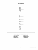
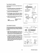
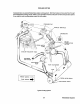
Leaving the dial gauge set condition unvaried, depress the spring stopper
(1)
and slide the torque spring
set support spring case (2). Read the deflection
of
dial gauge which corresponds
to
the projection of the
spring stopper from the spring case. (Measurement should be made
two
or
three times repeatedly
to
make sure
of
accurate measure.) For the models which
do
not require any torque spring action, set the
projection
(8)
to
a value in the range
of
0
to
-0.4.
4.
After adjustment, tighten nut
(4)
to
a torque of 0.8
to
1.2 kgm.
5.
Check
to
see that the spring stopper
(1)
can be depressed smoothly and that the end face of the stopper
(1)
can become flush with the end face
of
the spring case (2).
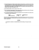
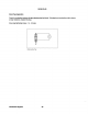
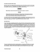
6.
For the purpose
of
identification
of
projection
(8),
apply paint of the color specified
to
the surface shown
in the figure at the right of paragraph
(1).
MQd.eL
206
Two & 306 Three
projection 8 mm
o
'"
-0.4
Identification color
Red
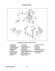
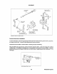
Replace the gear case and inspect the governor. When removing the gear case, be sure
to
remove the
tie-rod cover
by
the side
of
the fuel pump and disconnect the tie-rod from the rack. If any parts are found
defective, replace them.
CAUTION
If the governor is assumed
to
be malfunctioning, check the bearing on the gear case side,
too.
Westerbeke
Engines
64