TECHNICAL MANUAL WESTERBEKE 20B TWO 30B THREE MARINE DIESEL PROPULSION ENGINE Publication #037600 Edition One April 1990 j r~ 'WESTERBEKE J I WESTERBEKE CORPORATION· MYLES STANDISH INDUSTRIAL PARK 150 JOHN HANCOCK ROAD, TAUNTON, MA 02780-7319 U.S.A.
SAFETY PRECAUTIONS Be sure the unit and its surroundings are well-ventilated. The following symbols appear in this manual to call attention to and emphasize conditions potentially dangerous to the operator. • Use Extreme Care When Handling Engine Fuel (A constant danger of explosion or fire exists) IWARNINGI Do not fill fuel tank(s) while the engine is running. The above symbol is used in the manual to warn of possible serious personal injury or loss of life.
IMPORTANT PRODUCT SOFTWARE DISCLAIMER Product software of all kinds, such as brochures, drawings, technical data, operator's and workshop manuals, parts lists and parts price lists, and other information, instructions and specifications provided from sources other than Westerbeke, is not within Westerbeke's control and; accordingly, is provided to Westerbeke customers only as a courtesy and service.
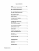
TABLE OF CONTENTS Section ......................................................................... Page 20B TWO GENERAL SPECIFICATIONS ............................9 20B TWO SYSTEM SPECIFICATIONS ............................10 30B THREE GENERAL SPECIFICATIONS ...................... 12 30B THREE SYSTEM SPECIFICATIONS ......................... 13 20BTWO AND 30B THREE ENGINE SERVICE SPECIFICATIONS .............................15 ENGINE OVERHAUL ........................................................
TABLE OF CONTENTS (CONTINUED) STARTER .......................................................................... 71 ALTERNATOR .................................................................. 78 ENGINE TROUBLESHOOTING ....................................... 85 MARINE TRANSMISSIONS ............................................. 88 TABLE OF STANDARD HARDWARE TIGHTENING TORQUES ........................... 89 SPARE PARTS .................................................................. 91 INDEX .............
...
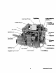
,FreSh W_ Fill CaP~ ~ !VI ll'ilake Silenger Zinc I'\mJUt:i~ Fuellnjeciion~. Pump - .
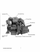
. .. fresh Water Fill Cap Ge~r Shift l:,ever :50 Amp ~t~rnator AdJU;;'LQU',\;; :Engine Isolator Starter with Solenoid' . - Westerbeke Engines DC .
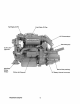
.Air Intake Silel'!cer .~reh~t Solenord Fuel Injection Pump / ThrotHe and Shut-Off Connections 20 Amp DC Circuit Zinc Anode Oil Pressure /SW~l! Gear Dipstick and Oil Filler ... Adjustable Engine Isolator . Lube Oil . Drain Ho~~~ Fresh Water Block Drain Plug 7 Westerbeke Engines .
UNIT 1.0. PLATES • MODEL SPEC . AVO .. MA USA SER.NO.. 20B TWO UNIT 1.0. PLATE • MODEL SPEC AVO" MA USA SER.NO.. 30B THREE UNIT 1.0. PLATE The unit 1.0. plate is attached to the exhaust manifold of the engine. These illustrations are provided so that the owner/operator may transcribe the specifications and serial number from the 1.0. plate on the engine to one of the illustrations above. This will allow for easy reference when seeking parts, service or technical needs.
20B TWO MARINE DIESEL ENGINE GENERAL SPECIFICATIONS Engine Type Diesel, four-cycle, two-cylinder, fresh water-cooled. Vertical, in-line, overhead valve mechanism (18 hp at 3600 rpm maximum). Governor Mechanical, centrifugal weight type. Combustion Chamber Swirl type. Bore & Stroke 2.99 x 2.76 inches (76 x 70 mm) Piston Displacement 38.75 cubic inches (0.635 liters) Firing Order 1-2 Direction of Rotation Clockwise, when viewed from the front. Maximum Torque (at 2200 rpm) 30 Ib-ft (4.
20B TWO MARINE DIESEL SYSTEM SPECIFICATIONS FUEL SYSTEM General Open flow - totally self-bleeding, manual priming. Fuel No.2 Diesel (cetane # 45 or better). Injector Pump In-line plunger type (Bosch type). Engine Timing (spill timing) 19° ±1° BTDC Static Injector Pressure 1991 psi (140 kg/cm2) Nozzle Throttle type. Lift Pump 12-volt DC; lift capacity 5 ft (1.5 m) PN 037818 Air cleaner Plastic screen type - cleanable. Air Flow (engine combustion) 40.6 cfm (1.
208 TWO MARINE DIESEL SYSTEM SPECIFICATIONS Oil Filter PN 036918 Full flow, paper element, spin-on type. Sump Capacity (including filter) 3.0 U.S. qts (2.9 liters) Operating Oil Pressure (engine hot) 15 - 45 psi (1.0 - 3.1 kg/cm2 ) Oil Grade API SPECIFICATION OF CF OR CG-4 ELECTRICAL SYSTEM Starting Battery 12-volt, 26 A-H, (-) negative ground (recommended) (35 A-H in cold areas) Battery Capacity 90 -125 (ampere-hours) Starter PN 034552 12-volt, 1.2 t
30B THREE MARINE DIESEL ENGINE GENERAL SPECIFICATIONS Engine Type Diesel, four-cycle, three-cylinder, fresh water-cooled. Vertical, in-line, overhead valve mechanism (27 hp at 3600 rpm maximum). Governor Mechanical, centrifugal weight type. Combustion Chamber Swirl type. Bore & Stroke 2.99 x 2.76 inches (76 x 70 mm) Piston Displacement 59.09 cubic inches (0.952 liters) Firing Order 1-3-2 Direction of Rotation Clockwise, when viewed from the front. Maximum Torque (at 2200 rpm) 43 Ib-ft (5.
30B THREE MARINE DIESEL SYSTEM SPECIFICATIONS FUEL SYSTEM General Open flow - totally self-bleeding, manual priming. Fuel No.2 Diesel (cetane # 45 or better). Injector Pump In-line plunger type (Bosch type). Engine Timing (spill timing) 19° ±1° BTDC Static Injector Pressure 1991 psi (140 kg/cm~ Nozzle Throttle type. Lift Pump PN 037818 12-volt DC; lift capacity 5 ft (1.5 m) Air cleaner Plastic screen type - cleanable. Air Flow (engine combustion) 60.4 cfm (1.
30B THREE MARINE DIESEL SYSTEM SPECIFICATIONS Oil Filter PN 036920 Full flow, paper element, spin-on type. Sump Capacity (including filter) 3.7 U.S. qts (3.5 liters) Operating Oil Pressure (engine hot) 15 - 45 psi (1.0 - 3.1 kg/cm2 ) Oil Grade API SPECIFICATION OF CF OR CG-4 ELECTRICAL SYSTEM Starting Battery 12-volt, 26 A-H, (-)negative ground (recommended) (35 A-H in cold areas) Battery Capacity 90 - 125 (ampere-hours) Starter PN 034552 12-volt, 1.2 KW, reduction type, solenoid-mounted.
20B TWO AND 30B THREE ENGINE SERVICE SPECIFICATIONS NOTE: All dimensions and specifications contained in this section are given in inches then millimeters unless otherwise stated. For example, 0.002 (0.5 mm). Specified Value/Standard Repair Limit 398.16 psi (at 280 rpm) (28 kg/cm~ 355.5 psi (25 kg/cm2) Cylinder Compression Pressure Difference Between Cylinders (maximum) 35.55 psi (2.
Specified Value/Standard Repair Limit Valves Valve clearance (IN & EX) 0.010 (cold) (0.25 mm) Valve head dia. (IN) 1.051 (26.7 mm) (EX) 0.972 (24.7 mm) Overall length 3.701 (94 mm) StemO.D. 0.260 (6.6 mm) Stem to guide clearance (IN) 1.051 (Service limit) (26.7 mm) (EX) 0.972 (Service limit) (24.7 mm) Valve face angle Valve head thickness (margin width) 0.039 (1.0 mm) Valve head sinkage (From cylinder head to bottom face) 0.020 0.5mm Valve Spring Free length 1.595 (40.
Specified Value/Standard Repair Limit Rocker Arm Rocker arm 1.0. 0.472 (12 mm) -0.008 (Service limit) (-0.2 mm) Rocker arm to shaft clearance Cylinder Block Camshaft hole dia. Front 1.654 Ball bearing hole (42 mm) NO.2 No.3 1.339 (34 mm) (30B Three only) 1.299 (33 mm) Rear 1.299 (33 mm) Cylinder Bore Bore size Oversize finish tolerance 2.992 (76 mm) +0.008 (+0.2 mm) o - 0.001 for each oversize (0 -0.03 mm) Cylindricity Within 0.0004 (0.01 mm) Gasket fitting/surface distortion Within 0.
RepairUmit Specified Value/Standard Piston (continued) 0.01, 0.02, 0.03 (0.25, 0.50, 0.75 mm) Oversize 0.035 (0.9 mm) Protrusion from cylinder block top surface Piston Pin Type Semi-floating type 0.0. 0.709 (18 mm) 0.003 (Service limit) (0.08 mm) Piston pin to piston clearance Piston pin to connecting rod clearance Press-fit load: 2204.6 ±1102.3Ibs. (1000 ±500 kg) Piston Rings Number of rings Compression (2) Oil (1) No.1: Chrome plated, semi-keystone type No.
Specified Value/Standard Repair Limit Connecting Rod Forged I-beam Type Within 0.002 (0.05 mm) Bend and twist 0.004 - 0.014 (0.1 - 0.35 mm) Big end thrust clearance Connecting Rod Bearing Aluminum metal with back metal Type Oil clearance 0.006 (Service limit) (0.15 mm) 0.01,0.02 (0.25, 0.50 mm) Undersize Crankshaft Type Fully counterbalanced Bend Within 0.001 (0.03 mm) End play 0.002 - 0.007 (0.05 - 0.175 mm) Journal 0.0. 1.693 (43 mm) -0.006 (-0.15 mm) Pin 0.0. 1.575 (40 mm) -0.
Specified Value/Standard RepairUmit Main Bearing Type Aluminum metal with back metal (No.2: Flanged metal) Oil clearance 0.01,0.02 (0.25, 0.50 mm) Under size Camshaft Gear drive Driving method Ball bearing Front journal 0.006 (Service limit) (0.15 mm) Journal to cylinder block hole clearance 1.078 (27.37 mm) Major diameter of cam (IN and EX) Oil clearance 0.006 (Service limit) (0.
Oil Specification TEMPERATURE c" F" ENGINE OIL [SRE I) -30 -20 -20 o -10 o 20 Dii' mmmwn _un 10 40 20 GO 30 80 40 50 100 120 NBI""'' ',!'' ' WhWuj> NOTE: API SPECIFICATION OF CF OR CG-4 IN ACCORDANCE WITH THE THERMAL ENVIRONMENT (SEE TABLE).
NOTES Westerbeke Engines 22
ENGINE OVERHAUL Section ..........................................................................Page PREPARATIONS FOR OVERHAUL ................................. 24 ENGINE DISASSEMBLY .................................................. 25 CYUNDER HEAD CONSTRUCTION AND SERVICING .............................................................. 26 VALVES AND VALVE SPRINGS ....................................... 30 VALVE CLEARANCE ADJUSTMENT ............................... 33 GEAR CASE AND OIL PUMP .............
PREPARATIONS FOR OVERHAUL 1. Shut off and disconnect all fuel lines, raw water and exhaust connections. 2. Unbolt the engine and carefully move it to the overhaul shop. 3. Once at the overhaul shop, drain all lubricating oil and coolant from the engine and exchanger system. 4. Clean the engine's exterior of all dirt and oil deposits. ~1\1\'\llllllllllIIIIIHl\iI!I"H'iH::~;H~r 1\I,j' \' i'i 'i";',' " i,' . \111.1 :.*':: I' . :;" l '. I: .- ..,,' ..
ENGINE DISASSEMBLY This section describes the disassembly of the engine when performing a complete overhaul of the unit. The procedures which follow include the disassembly of subassemblies, inspection of their components parts, repair or replacement of these parts (if necessary), and the reassembly of the subassemblies. Removal of External Parts and Subassemblies 1. Remove the exhaust manifold and related hoses as a unit. Disassemble and inspect these parts. 2.
CYLINDER HEAD CONSTRUCTION AND SERVICING ~ ~~~ @ .• ~~ ~--I' •.F----J. -=---ej) Cylinder head a cross section CYLINDER HEAD COMPONENT PARTS 1. Cylinder head. 2. Valve guide. 3. Cylinder head bolt (main bolt). 4. Cylinder head bolt (sub-bolt). 5. Seat ring (3600 rpm specification engine). Westerbeke Engines 26 6. Water outlet fitting. 7. Cylinder head gasket. 8. Mouth piece. 9. Thermostat. 10. Thermostat fitting.
Cylinder Head Removal 1. Remove the high pressure injection line assembly. CAUTION When disconnecting each injection line from the injection pump side delivery valve holder, grasp the holder with a wrench to prevent it from loosening. After removing the pipe assembly, plug the nozzle holders and delivery valve holders to prevent intrusion of dust. 2. Disconnect the glow plug lead wire. 3. Disconnect the air breather hose. 4. Remove the rocker cover. 5. Remove the rocker shaft assembly. 6.
Cylinder Head Inspection and Repair Check cylinder head surface for warpage between bolt holes: within O.05mm Check guide for ware and damage. Check for cracks, damage, water leak and remove oil, sludge, sealant deposit, carbon deposit. Check for valve contact, wear, damage, and sink of seat face. Valve Guide Replacement (\625) (\612) If a valve guide is found defective. replace it. (\66.6 i 1. Remove the valve guide by pressing at its upper end and pull it out to the valve seat side. I 2.
Valve Seat Repair Valve sinkage If a valve seat is found defective, reface it or replace the cylinder head. Sinkage of valve Interface and wear Standard Service limit 0.5 mm 1.5 mm Checking Valve Sinkage CAUTION When checking valve sinkage, the valve guide must be in normal condition. Resurface the valve seat so that it contacts the mid-portion of the valve face.
VALVES AND VALVE SPRINGS ~=---':~' ~--(2) ..----@ VALVE SYSTEM COMPONENT PARTS 1. Valve stem cap. 2. Retainer lock. 3. Valve spring retainer. Westerbeke Engines 4. Valve stem seal. 5. Valve spring. 6. Valve.
Valve Removal 1. Dismount the cylinder head assembly. 2. Depress the valve retainer (to compress the valve spring) and remove the retainer lock. 3. Remove the valve. Valve Inspection and Repair If any parts are found defective, repair or replace them. Q------ Wear and damage (Without for agricultural) ~~ @ Dents and wear I - - - - - R i d g e and damage Margin Inspection of Valve and Valve Spring Valve fatigue and damage Inspection item Standard Service limit Free length (Dim) 40.
1. If the valve face is found worn down, resurface it with a valve refacer. If the margin of the resurfaced valve exceeds the service limit, replace the valve. I--- f-- 2. If the valve stem end has been indented by wear, flatten it with an oil stone. ./ " , - -- /~------"'..." 45" \ / / ~Margin t• / I Inspecting Valve Valve and Valve Spring Installation 1. Install the valves and valve springs, referring to notes shown in the figure below. 2. Mount the cylinder head assembly. 3.
VALVE CLEARANCE ADJUSTMENT Valve Clearance Adjustment Cylinder head bolts lIl.USt. be retightened before adjusting the valve clearance. When retightening the cylinder head bolts, draw out coolant, loosen the bolts slightly, and then retighten the bolts to the specified torque in the numerical order illustrated at right. Tightening torque: M10 bolt 54.2 - 61.5 Ib-ft (7.5 - 8.5 kg-m) M8 bolt 10.8 - 15.9 Ib-ft (2.0 - 3.
GEAR CASE AND OIL PUMP (Ii) '!}) GEAR CASE COMPONENT PARTS 1. 2. 3. 4. Bushings. Plug. Gear case. Front oil seal. Westerbeke Engines 5. 6. 7. 8. Relief plunger. Relief spring. Oil pump inner gear. Oil pump outer gear. 34 9. Oil pump housing. 10. Gear case gasket. 11. High-pressure pump gear housing. 12. Housing gasket.
Gear Case and Oil Pump Removal and Inspection 1. Remove the crankshaft pulley. 2. Remove the fan and fan belt. 3. Remove the tie-rod cover from the side face of the injection pump. 4. Remove the tie rod and tie rod spring. Be careful not to let the spring fall into the case. 5. Remove the governor cover assembly. 6. Remove the water pump assembly. 7. Remove the alternator. 8. Remove the pump housing. 9. Remove the gear case assembly. Check the removed parts.
Front Oil Seal Replacement 1. Remove the front oil seal. 2. Press-fit the new front oil seal. CAUTION Apply a thin coat of engine oil to the circumference and lip of the oil seal. Governor Shaft Bushings' Replacement 1. Remove the expansion plug and draw the bushings out. 2. Press-fit the new bushings into positions shown in the figure at right. To be flush with this plane To be in contact with bottom Press· fitting Governor Shaft Bushing Governor System Inspection Check springs for fatigue.
Governor Levers' Disassembly and Reassembly Expansion plug 1. Removal of the shaft. Grooved pin Projection approx.2mm a. Remove the expansion plug, taking care not to scratch the gear case. b. Pull out the grooved pin. Section A-A 2. Installation of the shaft. Gear case a. Install the shaft in the reverse order of removal. Installing Governor Shaft b. After installing the shaft, press-fit the expansion plug into the shaft hole in the gear case. Gear Case Installation Tightening torque O.8-1.0kg.
TIMING GEARS "'4 Cj) TIMING GEAR COMPONENT PARTS 1. Crankshaft gear. 2. Idle gear. Westerbeke Engines 3. Camshaft gear. 4. Injection pump camshaft gear.
Timing Gears' Removal 1. Pry the snap ring out and remove the idle gear. 2. Remove the valve camshaft and injection pump camshaft on which the respective gears are press-fitted. Remove the gears from the shafts. 3. Remove the crankshaft. Remove the gear from the crankshaft. Timing Gears' Inspection Check the removed gears. If any gear is found defective, replace it. Injection pump camshaft gear -r....-,,,.: _ / Check tooth faces and end surfaces for wear and damage.
Timing Gears' Installation 1. Press-fit the crankshaft gear onto the shaft. 2. Press-fit the valve camshaft gear and injection pump camshaft gear onto the respective shafts. 3. Install the gears in the following sequence. a. Turn the crankshaft to set the No. 1 cylinder to top dead center on compression stroke. Idler Gear (Note timing marks1&2) b. Install the valve camshaft and injection pump camshaft. c. Install the idle gear so that timing marks on it are in alignment with marks on the other gears. d.
CAMSHAFTS (Valve and Pump) @ @ @ I ~~ rID @ (1) CAMSHAFT COMPONENT PARTS 8. Tappet. 9. Push rod. 10. camshaft (injection pump). 11. camshaft gear. 12. Ball bearing (rear). 13. Snap ring. 1. Camshaft (valve). 2. Camshaft gear. 3. Ball bearing. 4. Woodruff key. 5. Sunk key. 6. Camshaft stopper.
Valve Camshaft Removal 1. When it is necessary to remove only the valve camshaft, use the following procedure. a. Dismount the cylinder head assembly. b. Pull out the push rods. c. Pull out the tappets. d. Remove the gear case assembly. e. Remove the camshaft stopper bolt. f. Draw the camshaft assembly out. 2. Removal of the injection pump camshaft. a. Disconnect the injector lines. b. Remove the injection pump assembly. c. Remove the gear case assembly. d. Remove the shaft rear cover. e.
Camshafts' Inspection Cam lobe-Wear and damage Bend--- End face-Wear and damage Journal bearing-Wear and damage Each ball bearing-Wear and noise Cam contact surface-Wear and damage Cam lobe-Wear and damage Oldham's coupling-Wear Inspection of Camshafts Major diameter of injection pump cam Major diameter of valve cam Standard value 30 Standard value 27.37 Service limit -0.7 Service limit -1.
Camshafts' Installation When installing the camshafts, give care to the following. 1. Coat the bearings and cam lobes with oil. 2. Install the camshafts in the reverse order of removal. 3. Position the timing marks on the gears in alignment with the marks on the idler gear. 4. After installation, check and adjust fuel injection timing and valve clearances.
PISTON AND CONNECTING ROD Os-=-- : ---(J) €3 1_ ' ! l 1 (~)~ €!---I ~" (8)--IQ' PISTON AND CONNECTING ROD COMPONENT PARTS 1. Piston ring No.1. 2. Piston ring No.2. 3. Oil ring. 4. Piston. 5. Piston pin. 6. Connecting rod. 7. Connecting rod bearing. 45 8. Connecting rod cap. 9. Connecting rod bolt. 10. Connecting rod nut.
Piston and Connecting Rod Removal 1. Remove the cylinder head assembly. 2. Remove the oil pan. 3. Remove the oil screen. 4. Chalk the cylinder number on the side face of the big end of each connecting rod to prevent confusion of connecting rods. 5. Remove the connecting rod cap from each piston and rod assembly and draw the assembly upward from the cylinder. Take care not to allow the connecting rod to scratch the crankshaft pin and cylinder. Keep the removed parts (connecting rod, rod cap, piston etc.
Inspection of piston ring gaps. Put each piston ring into the cylinder bore and push the ring with the piston to position the ring on square with the cylinder wall. Measure the ring gap with a feeler gauge. If the measurement exceeds the service limit, replace that piston ring. Piston o Cylinder CAUTION Ring When only the replacement of rings is to be made, without reboring (honing) of the cylinder, position the ring to be measured at the least worn place of the cylinder skirt.
Pressing Push rod Connecting rod FRONT mark (arrow) ', .....~~-- Tool body 2. Installation of piston rings. FRONT mark - - -..... Ring set positions: No.1 ring. No.2 ring. oil ring d ~ "r mark and OS size mark "r mark and OS size mark Rod front --.------~ mark OS size identification paint Align notches accurately with each other. Color of discrimination STO =Without color O.25=White O.50=Blue Tightening torque: ____{O"\ 3.2-3.5kg.
3. Set the piston ring gaps to the proper positions as shown in the figure at right. Coat the rings and cylinder wall with oil. Ol'ri"if ~ ~ Front ~ ~ No.2 ring No.1 ring gap gap~ ,J!." 0' 0011 expander of oil ring Proper Arrangement of Ring Gaps 4. Using a piston ring compressor to compress the rings into the grooves, push the piston and rod assembly down into the cylinder. Be careful not to break the rings by excessively knocking the head of the piston.
CRANKSHAFT ® CRANKSHAFT COMPONENT PARTS 1. Key. 2. Crankshaft. 3. Crankshaft gear. 4. Crankshaft pulley. 5. Nut. Westerbeke Engines 11. Rear oil seal case. 6. Washer. 7. Spring washer. 12. Gasket. 8. Flywheel. 13. Flywheel bolt. 9. Ring gear. 10. Rear oil seal.
Crankshaft Removal 1. Loosen the flywheel bolts and remove the flywheel. 2. Loosen the crankshaft pulley nut and remove the pulley. 3. Remove the rear oil seal case assembly. 4. Remove the main bearing caps. 5. Take out the crankshaft. Crankshaft Inspection Inspect the removed parts. If any parts are found defective, repair or replace them. • Journals and pins- Damage and uneven wear • Cracks.
Checking the crankshaft for wear. To check the crankpins and main journals for tapering wear and out-of-round wear, the diameter of each crankpin or main journal should be measured at two places along the crankpin or main journal, in two directions "A" and "B" each place, as shown in the figure at right. If necessary, regrind the crankpins and main journals to the next under size. If any crankpin or main journal has been worn out beyond the service limit, replace the crankshaft.
Crankshaft Rear Oil Seal Replacement 1. Pry the oil seal out with a screwdriver. 2. Drive in a new oil seal to the oil seal case. When installing the crankshaft, pay attention to the notes given in the figure below. Cap tightening torque: 5.0- 5.5kg.m Thrust bearing only for No.2 cap J Side seals coated with sealant , 7-'ONO "'" Direction of installation of cap -\ 9 .-J~ Round end down Front Make cap flush with cylinder block end face (common to front and rear end faces) Crankshaft end play: 0.
CYLINDER BLOCK CYUNDER BLOCK COMPONENT PARTS 1. Cylinder block. 2. Front plate. 3. Bearing cap. 4. Cover. Westerbeke Engines 5. Main bearing. 6. Starter bracket. 7. Rear oil seal. 8. Oil seal case. 54 9. Idler gear shaft. 10. Oil filter shaft. 11. Oil level gauge guide.
Cylinder Block Inspection Inspect the cylinder block. If it is found defective, repair or replace the block. Cylinder Bore (mm): Mgdel 20B 30B Standard 76 + 0.03 -0.0 76 + 0.03 -0.0 A pprox.10mm from upper end Front Wear Umit Before Rebore: + 0.02 mm - Lower '-- ~ ~\J7 Center , Direction of measuing Measuring position Cylinder Bore Measuring Positions Cylinder Reboring When reboring a cylinder, use the following procedure. 1. Select a piston size: 0.25 as or 0.50 as. 2.
FUEL INJECTION PUMP INJECTION PUMP COMPONENT PARTS 1. Union collar. 8. Delivery valve. 9. Gasket. 3. Delivery valve holder. 10. Seat valve. 4. Valve spring. 11. Plunger barrel. 5. Holder stopper. 12. Sleeve. 6. Housing. 13. Upper seat. 7. O-ring. 14. Plunger spring. Westerbeke Engines 56 15. Plunger. 16. Lower seat. 17. Adjusting shim. 18. Tappet roller. 19. Pin. 20. Control rack. 21. Stop wire bracket.
Injection Pump Inspection while on the Engine Inspection Inspection procedure Never attempt to disassemble the pump unless it is necessary. If the pump is assumed defective, it is recommended to replace the pump assembly. Idling speed Measure engine speed. Criterial 900+ sgrpm I) Quickly accelerate Exhaust smoke color No remarkably black· engine without load. smoke exhaust permitted.
Injection Pump Assembly 1. Insert the plunger barrel into the housing. 2. Install the delivery valve and valve spring. Temporarily tighten the holder. 3. Insert the control rack. 4. Insert the control pinion. Align the matchmark on the rack with that on the pinion. 5. Install the spring upper seat. 6. Insert the plunger spring. 7. Fit the lower seat to the plunger. Insert the plunger into the barrel side. 8. Depress the tappet roller assembly and install the stopper pin. 9. Tighten the delivery holder.
INJECTION NOZZLE @:_-- I ::g <9 @ @ @ NOZZLE HOLDER ASSEMBLY COMPONENT PARTS 1. Body subassembly. 2. Shim washer. 3. Pressure spring. 4. Pin. 5. Distance piece. 6. Nozzle assembly. 7. Retaining nut.
Injection Nozzle Removal 1. Disconnect the injection pipe and fuel return pipe. 2. Remove the injection nozzle assembly from the cylinder head. CAUTION Attach an identification number tag to the removed injection nozzle. Plug the openings from which the pipes are disconnected and the nozzle is removed to prevent intrusion of dust, water, and other foreign particles into the pipes and combustion chamber.
Injection Nozzle Adjustment Adjust injection start pressure by increasing or decreasing the thickness of the shim washer to be inserted. Varying shim thickness by 0.1 mm causes injection start pressure to change 10 kg/cm. Tightening torque: 2.5-3.0kg.m Tightening torque: 3.5-4.0kg.m 10 kinds of shims available from 1.25 mm to 1.7 mm in thickness, 0.05 mm step. Injection start pressure Return pipe Standard Allowable limit Assembling the Nozzle 130 kg/ an' or less Injection Nozzle Installation 1.
GOVERNOR SYSTEM I---@ ® GOVERNOR SYSTEM COMPONENT PARTS 1. Sealing metal. 2. Sealing wire. 3. Low and high speed. 4. Governor spring. 5. Sliding shaft. 6. Stopper 7. Governor spring. 8. Governor shaft. 9. Governor lever. 10. Tie-rod. Westerbeke Engines 11. Tie-rod clip. 12. Tie-rod cover. 13. Tie-rod cover gasket. 14. Tension lever 15. Start spring. 16. Governor spring lever. 17. Speed control lever assembly. 18. Cover assembly. 19. Governor cover gasket. 20. Return spring. 62 21.
Torque Spring Set Installation Torque spring set Install and adjust the torque spring set using the following procedure: 1. Set the speed control lever to the high idling speed position by adjusting the high speed set bolt. Turn in this torque spring set until engine speed drops about 50rpm from high-idling speed. 2. Turn in the torque spring set until engine speed drops about 50 rpm from high idling speed. 3. From this position, turn back the torque spring set by the specified number of turns (N).
3. Leaving the dial gauge set condition unvaried, depress the spring stopper (1) and slide the torque spring set support spring case (2). Read the deflection of dial gauge which corresponds to the projection of the spring stopper from the spring case. (Measurement should be made two or three times repeatedly to make sure of accurate measure.) For the models which do not require any torque spring action, set the projection (8) to a value in the range of 0 to -0.4. 4.
GOVERNOR ~GJ Check springs for fatigue. ~~\d)./ Check levers for smooth movements. 7 ~\,i) Check springs for fatigue. ~~ Check shaft for flaws. Check sliding sleeve joint for wear and damage. Check weight for wear and damage. Check sliding sleeve for wear, damage and smooth movement. Inspection Governor System Parts Governor Removal and Installation To remove the levers, pull out the grooved pins which have been driven into the governor lever, stop lever, and speed control lever.
GLOW PLUG Glow Plug Inspection Check for conduction between the glow plug terminal and body. Ifthe plug is not conductive at all or shows a large resistance, replace the plug. Glow plug tightening torque: 1.5 - 2.0 kgm.
COOLING SYSTEM Illustrated below is a typical Westerbeke engine cooling system. Both fresh water and raw waterflow through their independent cooling circuits. Refer to your generator's Parts List for part numbers and part descriptions if you need to order cooling system parts for your engine. INJECTED E~- _ _ _ _ _ PRESSURE CAP EXHAUST MANIFOLD WATER ~'r---=~-_ TEMPERATURE .~~"'1' SWITCH {7' INCOMING RAW WATER FRESH WATER ~ FRESH WATER DRAIN RAW WATER . . .
Fresh Water Pump Drive BeH Tension Generator models come equipped with belt guards that cover over the belt(s) on the front of the engine. ("Out of sight-out of mind." The belt guard is not installed for that purpose.) Operators are advised that the inspection, service, and maintenance spoken of below should be followed. IWARNINGI Never attempt to adjust the drive belt's tension while the engine is in operation.
Raw Water Pump Overhaul Raw water pump #033636 repair instructions are as follows: Disassembly The pump, as removed from the engine, will have hose attachment nipples threaded into the its inlet and outlet port. They may be left in place or removed if they interfere with the pump disassembly. Note the port location and positioning if removed. a. Remove the six cover plate screws (ref 13), cover plate (ref 12) and the cover plate gasket (ref 11).
Assembly a. Install the seals (ref 7) and spacer (ref 14) in the pump housing. Push the impeller side seal into the housing. Rotate the pump and install the spacer (ref 14) against the seal face. Push the bearing side seal into the housing from the bearing side. NOTE: The seal's flat surfaces, having printing and numbers, face towards each other. b. Install shaft (ref 8) into bearings. Support bearings (ref 2) at their center race.
STARTER (,!l) I}) lID .~~ STARTER COMPONENT PARTS 1. Front bracket assembly. 2. Lever assembly. 3. Spring set. 4. Center bracket assembly. 5. Switch assembly. 6. Through bolt. 7. Armature. 8. Rear bearing. 9. Pinion. 10. Pinion shaft assembly. 71 11. Gear. 12. Yoke assembly. 13. Brush holder assembly. 14. Rear bracket.
Starter Adjustment and Repair If any abnormality is assumed by the following tests, adjust the starter or disassemble and repair it. Push back Lightly 1. Pinion gap inspection. a. Interpose a battery (12 V) between the starter terminallS" and the starter body, and the pinion will protrude and stop. O.5-2.0mm CAUTION Never apply battery voltage for over 10 seconds continuously. Inspecting Pinion Gap b. Lightly push the pinion back and measure the return stroke (called pinion gap). c.
3. Magnetic switch. Perform the following tests. If any test result is not satisfactory, replace the magnetic switch assembly. a. Disconnect the wire from terminal "M." b. Attraction test. Connect a battery to the magnetic switch terminals Sand M. The pinion must protrude. Starter CAUTION Attraction Test Do not apply battery current for more than 10 seconds. c. Holding test. With a battery connected to the magnetic switch terminal "S" and to the starter body, manually pull out the pinion fully.
Starter Disassembly 1. Disconnect the wire from the magnetic switch terminaI M." I 2. Loosen the two screws fastening the magnetic switch. Remove the magnetic switch assembly. 3. Remove the two through bolts and two screws fastening the brush holder. Remove the rear bracket. 4. With two brushes brought in a floating state, remove the yoke and brush holder assembly. Then, pull the armature out. 5. Remove the cover, pry the snap ring out, and remove the washer. 6.
Starter Inspection Break and short circuit Wear and chipping Bearing: Play. noise. and rough rotation Insulation Bearing: Play. noise. and rough rotation Break and short circuit Inspect about the following: Description Standard Service limit Description Standard Service limit Depth of under cut 0.5 mm 0.2 mm Height of brush 17 mm 6 mm 38.7 mm -1.0 mm Spring pressure 3 kg Commutator O. D. 1.
2. Inspecting the armature. a. Check the armature with a growler tester. If it's short circuited, replace the armature. Also, check for insulation between the commutator and its shaft. If poorly insulated, replace the armature. b. Measure the commutator 0.0. and the depth of undercut. Repair or replace it if the service limit is exceeded. Also, check the commutator outside surface for dirtiness and roughness. If rough, polish the commutator with fine-grain sandpaper. Checking Armature Coil 3.
b. Measure end play by moving the pinion shaft in the axial direction. If the end play exceeds 0.5 mm, increase the number of adjusting washers inserted. 2. Greasing. Whenever the starter has been overhauled, apply grease to the following parts: 1. Armature shaft gear and reduction gear. 2. All bearings. 3. Bearing shaft washers and snap rings. 4. Bearing sleeves. 5. Pinion. 6. Sliding portion of lever. CAUTION Never smear the starter fitting surface, terminals, brushes, or commutator with grease.
ALTERNATOR @ I CD @ @ @ @ ALTERNATOR COMPONENT PARTS 9. Rectifier assembly. 5. Rear bearing. 1. Pulley. 10. Rear bracket assembly. 2. Front bracket assembly. 6. Stator. 11. Condenser assembly. 7. Terminal set. 3. Front bearing. 8. Regulator assembly. 4. Rotor assembly.
Alternator On-Engine Inspection 1. Erroneous handling can cause damage to the charging circuit and other troubles so avoid the following: a. Never connect the battery in reverse. b. Do not use a megger and other high-voltage testers. c. When recharging the battery, disconnect the battery cable from the alternator. d. Never disconnect the lead wire from the alternator terminal B while the engine is running. e. Never ground the alternator terminal B to which battery voltage is always applied. f.
e. Apply all load Including the lamps. Ammeter r-----~+~Ar-----~~ f. Increase engine speed until normal alternator speed is attained. Read the maximum indication of the ammeter at 13.5 V of voltmeter indication. Output current must conform to the specification. Checking for Output AHernator Removal Characteristic Terminal voltage (V) I Current (A) I 1. Disconnect the battery cable. 2. Disconnect the lead wire from terminal "S" on the back of the alternator.
5. Unsolder the stator coil lead wires. Remove the stator assembly. CAUTION Never heat the lead wires long to prevent damage to diodes. 6. Disconnect the capacitor from terminal liB. II 7. Loosen the screws fixing the rectifier and remove the rectifier. Alternator Inspection Inspect the disassembled parts, if any part is found defective, replace it.
2. Inspecting the field coil. a. Check for conduction between slip rings. If there is no conduction, the field coil is suspected to be broken. Replace the field coil. Checking Field Coil for Conduction b. Check for conduction between a slip ring and shaft (or core). If any conduction is found, the field coil is suspected to be poor in insulation. Replace the field coil. Checking Field Coil for Insulation 3. Inspecting the stator coil. a. Check for conduction between lead wires of the stator coil.
AHernator Assembly Reassemble the alternator assembly in the reverse order of disassembly giving care to the following: 1. The rear bearing has an eccentric groove. Install the snap ring so that its projection fits in with the deepest part of the groove. 2. When installing a new rear bearing, press-fit the bearing with its groove facing the slip ring side. 3. When press fitting the rear bearing into the rear bracket, heat the bracket.
NOTES Westerbeke Engines 84
ENGINE TROUBLESHOOTING possjble Cause Verifjcatjon/Correctjon 1. Connection or switch. 1. Check for 12 volts at the PREHEAT switch and at the S terminal on the preheat solenoid. 2. Preheat solenoid. 2. No activation with 12 volts at the S terminal. Tap solenoid with a mallet to determine if it is stuck internally. Solenoid should produce a click when activated and deactivated. 3. Glow plugs are faulty. 3. Twelve volts is present at the glow plugs.
.E.auI1 Possjble Cause Yerifjcatjon/Correctjon START switch is depressed: no starter engagement. Engine does not crank. 1. Connection to starter solenoid faulty. 1. Check connection S at the starter solenoid for 12 volts with the switch depressed. 2. Faulty start switch. 2. Check switch with an ohmmeter. 3. Faulty preheat solenoid. 3. Twelve volts is present at the S terminal of the starter solenoid. 4. Loose battery connection. 4. Check battery connections at both the + and - ground. 5.
Engine Stops. Battery runs down. Black exhaust smoke. possjble Cause Yerifjcatjon/Correctjon 1. Fuel starvation. Fuel shut-off is turned off. 1. Check to see that the shut-off valve at the fuel tank is on. 2. Fuel pump is inoperative. 2. Inspect the fuel pump for 12 volts and see if it is pumping. 3. Water is in the fuel. 3. Pump water out of the bottom of the fuel tank(s) and change the fuel filters and bleed the fuel system. 4. Exhaust system is restricted. 4.
MARINE TRANSMISSIONS JSGear The standard transmission on the 20B Two and 30B Three is the JS Gear. Contact Westerbeke Corporation factory for overhaul information. HURTH MARINE GEAR ZF INDUSTRIES MARINE US HEADQUARTERS 3131 SW 42ND STREET FORT LAUDERDALE, FL 33312 TEL. 954-581-4040 FAX 954-581-4077 BORG WARNER MARINE & INDUSTRIAL TRANSMISSIONS 200 THEODORE RICE BLVD NEW BEDFORD, MA 02745 TEL.
TABLE OFSTANDARD HARDWARE TIGHTENING TORQUES Unless stated otherwise for a specific assembly, use the following torque values when tightening standard hardware. Pitch Ib-ft kg-m ~rad~4T 6mni bolt head/nut 8mm bolt head/nut 10mm bolt head/nut 10mm bolt head/nut 12mm bolt head/nut 12mm bolt head/nut 12mm bolt head/nut 13mm bolt head/nut 14mm bolt head/nut 14mm bolt head/nut 16mm bolt head/nut 16mm bolt head/nut 1 1.25 1.25 1.5 1.25 (ISO) 1.5 1.75 1.5 1.5 2 1.5 2 2.9 - 5.1 7.2 - 11.6 13.7 - 22.4 13.0 - 21.
Cylinder head bolt Rocker shaft hold down bolts Socket Size .Lb:ft. &l:m M 10 (14 mm) 54 - 61 7.5 - 8.5 M 8 (12 mm) 14 -22 2.0 - 3.0 M 8 (12 mm) 11 - 16 1.5 '" 2.2 (See the "Cylinder Head" section of this manual.) Crankshaft pulley nut M 16 (24 mm) 72.3 - 86.7 10 -12 M 18 36.2 - 43.4 5.0 - 6.0· 8.0 - 9.4 (or tighten firmly by hand) 1.1 - 1.3 M 16 (17 mm) 25.3 - 28.2 3.5 - 3.9 . M 20 (21 mm) 36.2 -43.4 5.0 - 6.0 Fuel Solenoid Locknut M 30 (36 mm) 28.9 -36.2 4.0 - 5.
SPARE PARTS Since a possibility exists in which the engine may need to be serviced at sea or while in a port other than your home port, certain spare parts should be kept on board to help minimize delays in your voyage. Please refer to your engine's Parts List for part numbers when ordering spare parts. Listed below are those spare parts that should be carried on board at all times. 1. An impeller kit. 2. A fuel system hardware kit. 3. A secondary fuel filter element. 4. A water pump belt. 5. Hose clamps.
NOTES Westerbeke Engines 92
INDEX A ALTERNATOR ............................................................................................................................................. 78 Alternator Assembly .....................................................................................,.............................................. 83 Alternator Disassembly ............................................................................................................................... 80 Alternator Inspection ...............
Cylinder Bore ............................................................................................................................................... 17 Cylinder Compression Pressure .................................................................................................................15 Cylinder Head ..............................................................................................................................................15 CYLINDER HEAD CONSTRUCTION AND SERVICING .....
INJECTION NOZZLE .................................................................................................................................. 59 Injection Nozzle Adjustment ....................................................................................................................... 61 Injection Nozzle Assembly.......................................................................................................................... 60 Injection Nozzle Disassembly ..............................
S SPARE PARTS .............................................................................................................................................91 STARTER ......................................................................................................................................................71 Starter Adjustment and Assembly................•..............................................................................................76 Starter Adjustment and Repair ..................
NOTES 97 Westerbeke Engines