
User Manual


TB 45 51
.
13 Index
Index
!
2-point-correction 44
A
Accessories 46
Additional equipment 46
Analog output 28 - 30
Applications 5
B
Behaviour after supply v. on 17
C
Calibration (CAL)42
Cleasing 8
Configuration level (
ConF)
-
Configuration parameter 34 - 39
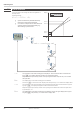
Connecting
-
Bus interface 12
-
di1 12
- Inp1 11
- Inp2 12
- Out1, Out2 12
- Out3 12
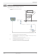
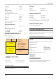
Connecting diagram 11
Connector 10
cULus approval 15
D
Dismounting 9
E
Extended operating level 19
F
Filter 25
Front view 16
Functions 21 - 32
H
Hints for installation 15
I
Input error detection 24
Input scaling 22 - 24
L
Limit values 26 - 27
Linearization 39
Logic output 29
M
Maintenance 8
Maintenance manager 31
Mounting 9 - 10
N
Number of switching cycles 28
O
O2-measurement 25
Offset-correction 43
Operating hours 28
Operating structure 17
Operation 16 - 20
P
Parameter level (PArA)
- Parameter 41
- Parameter survey 40
S
Safety hints 7 - 8
Spare parts 8
T
TAG -no. 20
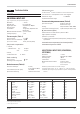
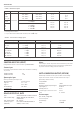
Technical data 47 - 50
Terminal connections 11 - 12
Transmitter supply 30
Two-wire measurement 24
V
Versions 46