
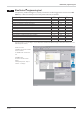
User Manual

Technical data
48 TB 45
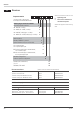
CONTROL INPUT DI1 (RESET)
Configurable as direct or inverse switch or push button!
Contact input
Connection of potential-free contact that is suitable for switching
‘dry’ circuits.
Switched voltage: 5 V
Switched current: 1 mA
Optocoupler input
Actively switched optocoupler input
Nominal voltage: 24 V DC external
Logic ”0”: -3 V…+5 V
Logic ”1”: 15 V…30 V
Current demand: max. 6 mA
OUTPUTS
RELAY OUTPUTS LC, OUT2
Type: 2 NO contacts with a common terminal
Max. contact rating: 500 VA, 250 VAC, 2A at 48...62 Hz,
resistive load
Min. contact rating: 6V, 1 mA DC
Switching cycles
(electrical):
for I=1A/2A: ? 800.000/500.000 (at
250VAC, resistive load)
Note:
If the relays LC and OUT2 operate external contactors, these must
be fitted with RC snubber circuits to manufacturer specifications
to prevent excessive voltage peaks at switch-off.
OUT3 AS UNIVERSAL OUTPUT (OPTION)
Galvanically isolated from the inputs. Parallel current/voltage
output with common ‘minus’ terminal (combined use only in
galvanically isolated circuits).
Freely scalable
Resolution: 14 bits
Dynamic response (step change of
input signal) T
90
:
Output follows the input:
ß 540 ms
Tracking error I/U: ß 2%
Residual ripple: (referred to end of
span)
ß_1%
0...130 kHz
Current output
0/4...20 mA, configurable
short-circuit proof
Control range: -0,5...23 mA
Load: ß 700 [
Type Sensor current Measuring range Accuracy Resolution (Ô)
Pt100***
ß 0,25 mA
-200...100 (150) °C -328...212°F ß 1K 0,1 K
0,1 K
0,1 K
Pt100 -200...850°C -328...1562°F ß 1K
Pt1000
-200...850°C -328...1562°F ß 2K
KTY 11-6* -50...150°C -58...302°F ß 2 K 0,1 K
Special
*
0...4500 [**
ß 0,1 %
ß 0,1 %
ß 0,1 %
ß 0,1 %
ß 0,1 %
0,01 %
0,01 %
0,01 %
0,01 %
0,01 %
Special 0...450 [**
Poti 0...160 [**
Poti 0...450 [**
Poti 0...1600 [**
Poti 0...4500 [**
* Default setting is the characteristic for KTY 11-6 (-50...150°C)
** Including lead resistance
*** Up to 150°C with reduced lead resistance (max. 160 [ total)
Table 2: Resistive inputs
Measurement range Input resistance Accuracy Typical resolution
0...20 mA 20 [ß0,1 % 1,5 mA
0...10 V » 110 k[ß0,1 % 0,6 mV
-10...10 V » 110 k[ß0,1 % 1,2 mV
-5...5 V » 110 k[ß0,1 % 0,6 mV
-2,5...115 mV* > 1 M[ß0,1 % 6,0 mV
-25...1150 mV* > 1 M[ß0,1 % 60,0 mV
-25...90 mV* > 1 M[ß0,1 % 8,0 mV
-500...500 mV* > 1 M[ß0,1 % 80,0 mV
-200...200 mV* > 1 M[ß0,1 % 40,0 mV
* For INP1: high-impedance, without break monitoring
Table 3: Current and voltage input