
User Manual

6.8 Maintenance manager / error list
In case of one or several errors, the error list is always displayed at the
beginning of the extended operating level .
A current input in the error list (alarm or error) is always indicated by display
of letter E .
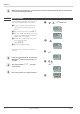
For display of the error list, press key ô once.
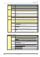
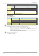
E- display
element
Description Possible remedial action
blinks
Alarm due to existing
error
- Determine the error type in the error list via the error number
- remove error
on
Error removed, Alarm
not acknowledged
- acknowledge alarm in the error list by pressing the È -orthe Ì -key
- the alarm entry is deleted by doing so
off no error, all alarm entrys deleted
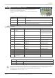
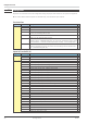
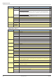
6.8.1 Error list::
Name
Description Cause Possible remedial action
E.1
Internal error, cannot be
corrected
E.g. defective EEPROM Contact PMA service
Return device to manufacturer
E.2
Internal error, resettable E.g. EMC trouble Keep measuring and supply ca
-
bles separate. Protect contactors
by means of RC snubber circuits
E.3
Configuration error, reset-
table
Missing or faulty configuration Check interdependencies for
configurations and parameters
E.4
Hardware error Code number and hardware not identical Contact PMA service
Replace electronics/options card
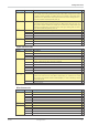
FbF.1
INP1 sensor break Defective sensor
Wiring error
Replace INP1 sensor
Check INP1 connection
Sht.1
INP1 short circuit Defective sensor
Wiring error
Replace INP1 sensor
Check INP1 connection
POL.1
INP1 polarity error Wiring error Change INP1 polarity
FbF.2
INP2 sensor break Defective sensor
wiring error
Replace INP2 sensor
Check INP2 connection
Sht.2
INP2 short circuit Defective sensor
Wiring error
Replace INP2 sensor
Check INP2 connection
POL.2
INP2 polarity error Wiring error Change INP2 polarity
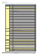
Lim.1
Latched limit value alarm 1 Adjusted limit value 1 exceeded Check process
Lim.2
Latched limit value alarm 2 Adjusted limit value 2 exceeded Check process
Lim.3
Latched limit value alarm 3 Adjusted limit value 3 exceeded Check process
Inf.1
Time limit value message Preset number of operating hours reached Application-specific
Inf.2
Switching cycle message
(digital outputs)
Preset number of switching cycles reached Application-specific
g
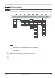
Latched alarms Lim2/3 (E element provided) can be acknowledged and reset via digital input di1 or via the
reset key function. The reset key function can be disabled using a password.
For Configuration, see ConF / LOGI / Err.r
Functions
TB 45 Maintenance manager / error list 31
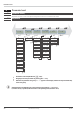
Error-state Signification
2 Pending error Change to error status 1after error removal
1 Stored error Change to error status 0 after acknowledgement in error list 0
0 no error/message Not visible, except during acknowledgement
1
2
TB
E
450.0
ûC
üüää