
User Manual
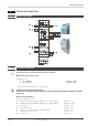
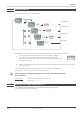
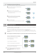

3 Connecting input di1
Digital input, configurable as a switch or a push-button.
a contact input terminals: 7, 8
b optocoupler input (optional) terminals: 7, 8
4 Connecting output LC / OUT2
Relay outputs max. 250V/2A as closer with shared contact connection.
w
LC terminals: 17, 18
w
OUT2 terminals: 17, 14
5 Connecting output OUT3
Universal output
h logic (0..20mA / 0..10V) terminals: 11, 12
i current (0...20mA) terminals: 11, 12
j voltage (0...10V) terminals: 12, 13
k transmitter power supply terminals: 11, 12
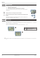
6 Connecting the bus interface (optional)
RS 485 interface with MODBUS RTU protocol
* see interface description MODBUS RTU: (9499-040-72011)
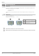
7 Connecting input INP2 (optional)
Input for the second variable INP2.
a thermocouple terminals: 5,6
b resistance thermometer (Pt100/ Pt1000/ KTY/ ...), 3-wire connection terminals: 2,5,6
c potentiometer terminals: 2,5,6
d current (0/4...20mA) terminals: 2,6
e voltage (-2,5...115/-25...1150/-25...90/ -500...500mV) terminals; 5,6
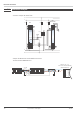
Electrical connections
12 Terminal connections TB 45