
User Manual

.
4 Electrical connections
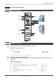
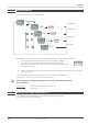
4.1 Connecting diagram
4.2
Terminal connections
a
Faulty connection can lead to the destruction of the instrument.
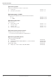
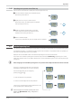
1 Connecting the supply voltage
Dependent on order
w
90 … 250 V AC terminals: 15,16
w
24 V AC / DC terminals: 15,16
For further information, see section 12 "Technical data"
g
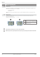
Instruments with optional system interface:
Energization is via the bus connector of field bus coupler or power supply module. Terminals 15, 16 must
not be used.
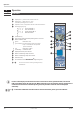
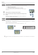
2 Connecting input INP1
Input for the measurement value
a resistance thermometer (Pt100/ Pt1000/ KTY/ ...), 3-wire connection terminals: 1, 2, 3
b resistance thermometer (Pt100/ Pt1000/ KTY/ ...), 4-wire connection terminals: 2, 3, 5, 6
c potentiometer terminals: 1, 2, 3
d current (0/4...20mA) terminals: 2, 3
e voltage (-2,5...115/-25...1150/-25...90/ -500...500mV) terminals: 1, 2
f voltage (0/2...10V/ -5...5V)) terminals: 2, 4
g thermocouple terminals: 1, 3
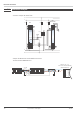
Electrical connections
TB 45 Connecting diagram 11
Data A
Data A
Data B
Data B
V
14
13
12
16
15
11
mV
17
18
INP2
INP1
OUT3
PWR
L
N
LC
OUT2
~90-250V
~24V
di1
8
76
3
2
1
5
3
4
(mV)
RGND
RGND
RS 485
1
2
a
3
4
5
6
7
b
c
d
e
f
g
a
b
c
d
a
b
Logic
V
h
i
j
k
e
11 12 13 14
11 12 13 14
15 16 17 18
15 16 17 18
1234
1234
top
16
15
17
18
System