
Manual

Load effect: ß 0,02%
Resolution: ß 1,5 úA
Error: ß 0,1%
Voltage output
0/2...10V, configurable
not continuously short-circuit proof
Control range: -0,15...11,5 V
Load: ? 2k[
Load effect: ß 0,06%
Resolution: ß 0,75 mV
Error: ß 0,1%
Additional error with simultaneous
use of current output
ß 0,09%
OUT3 as transmitter supply
Output: 22 mA / ? 13 V
OUT3 as logic signal
Load ≤ 700 [ 0/ß 23 mA
Load > 500 [ 0/> 13 V
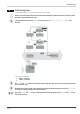
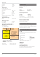
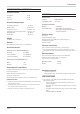
GALVANIC ISOLATION (FIG. 1)
Permissible voltages:
Safety isolation: ß 300 Vrms against earth
Functional isolation: ß 30 Vrms against earth
POWER SUPPLY
Depending on ordered version:
AC supply
Voltage: 90...250 V AC
Frequency: 48...62 Hz
Power consumption: approx 9 VA max.
Universal supply 24 V UC
AC voltage: 18...30 V AC
Frequency: 48...62 Hz
DC voltage: 18...31 V DC
Power consumption: Approx. 3 VA / W max.
Supply only from protective low-voltage sources (SELV)
Behaviour with power failure
Configuration and parameter settings:
Permanent storage in EEPROM
BLUEPORT
®
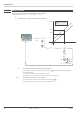
FRONT INTERFACE
Connection to the transmitter front via a PC adapter (see
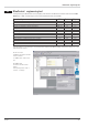
‘Accessories’). The BlueControl
® software enables the TB 45 to be
configured, parameters set, and operated.
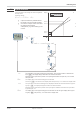
BUS INTERFACE (OPTIONAL)
RS 485
Connection via bus connector fitted in the top-hat rail. Screened
cables should be used.
Galvanically isolated
Type: RS 485
Transmission speed: 2400, 4800, 9600,
19.200, 38.400 bits/s
Parity: even, uneven, none
Address range: 1...247
Number of devices per bus segment: 32
PROTOCOL
•
Modbus RTU
SYSTEM INTERFACE
For connection to field bus coupler (s. System components)
Connection via bus connector in the top-hat rail.
Technical data
48 TB 45
Safety isolation
Function isolation
Power
Relay LC
Input 1
Input 2
di 1 (contact)
di 1 (option
optocoupler)
Output 3
RS 485
System
Relay 2
Front interface
Fig.1: galvanic isolation