PMA Prozeß- und Maschinen-Automation GmbH TB 45 Temperature limiter/monitor TB 45 TB 45 Operating manual English rail line 9499-040-93511 valid from: 02/2012
û BlueControl Ò More efficiency in engineering, more overview in operating: The projecting environment for the BluePortâ controllers,indicators and railline- measuring converters, universal controllers, temperature limiters on ! s ON ate TI Upd e.de N E d in l T a n D ATrsion ma-o A-C n M Ve w.
Content 1. General . . . . . . . . . . . . . . . . . . . . . . . . . . . . . . . . . . . . . . . 5 1.1 Application in thermal plants. . . . . . . . . . . . . . . . . . . . . . . . . . . . . . 6 2. Safety hints . . . . . . . . . . . . . . . 2.1 Maintenance, repair, modification . 2.2 Cleansing . . . . . . . . . . . . . . 2.3 Spare parts . . . . . . . . . . . . . . . . . . . . . . . . . . . . . . . . . . . . . . . . . . . . . . . . . . . . . . . . . . . . . . . . . . . . . . . . . . . . . . .
7. Configuration level . . . . . . . . . . . . . . . . . . . . . . . . . . . . . . . . . . . . 32 7.1 Configuration survey . . . . . . . . . . . . . . . . . . . . . . . . . . . . . . . . . 32 7.2 Configuration . . . . . . . . . . . . . . . . . . . . . . . . . . . . . . . . . . . . . 33 8. Parameter level . . . 8.1 Parameter survey 8.2 Adjustment . . . 8.3 Parameter level . . . . . . . . . . . . . . . . . . . . . . . . . . . . . . . . . . . . . . . . . . . . . . . . . . . . . . . . . . . . .
General . 1 General Thank you very much for buying a TB 45 temperature monitor. TB 45 temperature limiter are used for process monitoring. The units provide process value measurement, limit signalling and switch-off. Possible applications are heating and cooling processes. Configuration as an electronic temperature limiter, temperature monitor or as a limit signaller is possible. A TB 45 offers one universal input, one limit contact and one pre-alarm contact.
General 1.1 Application in thermal plants In many thermal plants, only the use of approved control instruments is permissible. TheTB 45 version (TB45-2xx-xxxxx-Dxx) meets the requirements as an electronic temperature limiter/monitor (TB/TW, type 2.B.J.V) according to DIN 3440 and EN 14597. This version is suitable for use in heat generating plants, e.g. in • • • • building heating systems acc. to DIN EN 12828 (formerly DIN 4751) large water boilers acc.
Safety hints . 2 Safety hints This unit was built and tested in compliance with VDE 0411-1 / EN 61010-1 and was delivered in safe condition. The unit complies with European guideline 89/336/EWG (EMC) and is provided with CE marking. The unit was tested before delivery and has passed the tests required by the test schedule. To maintain this condition and to ensure safe operation, the user must follow the hints and warnings given in this operating manual.
Safety hints 2.1 Maintenance, repair, modification The units do not need particular maintenance. There are no operable elements inside the device, so the user must not open the unit Modification, maintenance and repair work may be done only by trained and authorized personnel. For this purpose, the PMA service should be contacted. a l g Warning When opening the units, or when removing covers or components, live parts and terminals may be exposed. Connecting points can also carry voltage.
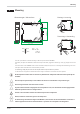
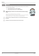
Mounting . 3 Mounting 4 3 2 6 7 K 8 te lem rm m in e / 1 al 5 Montage / mounting 5.5 (0,20”) Abmessungen / dimensions 2.3 (0,08”) 15 14 13 Demontage / dismantling 12 16 17 K 1 te lem 8 rm m in e / a 11 l 99 (3,90”) click 111 (4,37”) 22.5 (0,87”) 117.5 (4,63”) max. 55°C min. -10°C max. 95% rel. % 1 The unit is provided for vertical mounting on 35 mm top-hat rails to EN 50022. If possible, the place of installation should be exempt of vibration, aggressive media (e.g.
Mounting 3.1 Connectors The four instrument connectors are of the plug-in type. They plug into the housing from top or bottom and click in position (audible latching). Releasing the connectors should be done by means of a screwdriver. Two connector types are available: 2 • Screw terminals for max. 2,5 mm conductors 2 • Spring-clamp terminals for max. 2,5 mm conductors g Before handling the connectors, the unit must be disconnected from the supply voltage.
Electrical connections . 4 Electrical connections 4.1 Connecting diagram 2 INP1 a 5 6 7 8 1 2 3 4 b a 3 di1 1234 top c d e f g mV V RGND RGND Data A Data B Data A Data B RS 485 6 Logic 5 1 h k i j V OUT3 11 12 PWR 15 16 17 18 13 14 L N ~90-250V ~24V 15 LC OUT2 4 11 12 13 14 15 16 17 18 16 17 18 System 4.2 a Terminal connections Faulty connection can lead to the destruction of the instrument.
Electrical connections 3 Connecting input di1 Digital input, configurable as a switch or a push-button. a contact input b optocoupler input (optional) terminals: 7, 8 terminals: 7, 8 4 Connecting output LC / OUT2 Relay outputs max. 250V/2A as closer with shared contact connection. LC OUT2 terminals: 17, 18 terminals: 17, 14 5 Connecting output OUT3 Universal output h logic (0..20mA / 0..10V) i current (0...20mA) j voltage (0...
Electrical connections 4.3 Connecting diagram The instrument terminals used for the engineering can be displayed and printed out via BlueControl® ( menu File \ Print preview - Connection diagram).
Electrical connections 4.4 Connection examples Connection example: KS 45 and TB 45 L2 L1 KS 45 Fuse INP2 INP1 Fuse 5 6 7 8 1 2 3 4 Fuse TB 45 temperature limiter di1 INP1 5 6 7 8 1 2 3 4 di1 Resetbutton Contactor Heating SSR + _ Logic + + OUT3 11 12 13 14 11 12 13 14 PWR PWR 15 16 17 18 15 16 17 18 PWR PWR + LC N1 N2 Example: RS 485 interface with RS 485-RS 232 converter See documentation 9499-040-72011 Master z.B. / e.g.
Electrical connections 4.5 Hints for installation • • • • • a a a a TB 45 Measurement and data lines should be kept separate from control and power supply cables. Sensor measuring cables should be twisted and screened, with the screening connected to earth. External contactors, relays, motors, etc. must be fitted with RC snubber circuits to manufacturer specifications. The unit must not be installed near strong electric and magnetic fields.
Operation . 5 Operation 5.1 Front view 1 2 3 4 5 6 7 • • • • 8 9 0 ! § Display line 1: process value or limit value LC Display line 2: limit value LC / unit / extended operating level/ error list Operation mode “Temperature limiter” Error list (2 x ô ), e.g. • Fbf. x sensor fault INP. X • sht. x short circuit INP. X • Pol. x wrong polarity INP. X • Lim. x limit value alarm • ...
Operation 5.2 Operating structure Operation of the unit is divided into four levels: 450 °C äüäüü 1 2 TB E 3s ô operating level 450 ô PASS PARA äüäüüü parameter level. 1 2 TB E 450 CONF äüä ô PASS 1 2 TB E 450 CAL äüä configuration l. ô PASS 1 2 TB E 450 END äüä ô calibration l. 1 2 TB E With TB 45, access to parameter setting, configuration and calibration level is protected by a password. • The access to a level can be disabled by entry of a pass number (0 … 9999).
Operation 5.4 Displays at operating level 5.4.1 Display line 1 The value shown on display line 1 can be determined by configuration Dis1. This configuration is adjustable only via BlueControl®. The following values can be displayed: – process value (default) – limit value LC The display value, which is also called process value, is the value resulting from function 1. Normally, this is input value 1. 5.4.
Operation 5.4.3 Switching over by means of the Enter key Various values can be called up on display line 2 by pressing the Enter key. 1 The value defined for display line 2 (via BlueControl®); Basic setting is limit value LC. 1 278.3 450.0 äüä ô 2 Display of the error list, if it contains entries. With several entries, the following value is displayed when pressing the Enter key. 1 2 TB E 278.3 2 FbF. 1 ô ä ä 1 2 TB E ô 3 Display of extended operating level, if it contains entries.
Operation 5.6 Release function The following settings for error list resetting or limiting function releasing are available: • Resetting via digital input di1 • Resetting by pressing key combination Enter + Increment In the second case, press the Enter key first and keep it pressed whilst pressing the Increment key. g a 450 Pending alarms or error messages cannot be released. 1 2 TB E Please, note that the output or outputs are released when actuating the reset function.
Functions . 6 Functions The signal data flow of temperature limiter TB 45 is shown in the following diagram: Display INP Linearization Scaling/ Correction LC Func 1 INP1 Min* Max* Limit value OUT2 OUT3* di1 OUT3* * Option 6.1 Scaling (analog) Limiting functions TB 45 can be configured for various functions: • • • as a temperature limiter as a temperature monitor as a limit signaller 6.1.1 Temperature limiter If selected, a temperature limiter fun ction monitors the process value.
Functions 6.1.2 Temperature monitor The selected temperature monitor function monitors the process value. When the process value is above the adjusted high limit value LC or below the adjusted low limit value LC (configurable), output relay LC is opened and disabled. Release is automatic, when – the process value is below the adjusted high limit value LC (minus any adjusted hysteresis) again with setting ”Temperature monitor max.
Functions Ou.16 . . . . . . Ou.1 In.1 g 6.3 In.16 The linearization table is used for input 1 Input scaling Scaling of input values is possible. After any linearization, measurement value correction is according to the offset or two-point method. g When using current or voltage signals as input variables for InP.x, the input and display values shouldbe scaled at the parameter level. Specification of the input value of the lower and upper scaling point is in units of the relevant physical quantity.
Functions a For using the pre-defined scaling with thermocouples and resistance thermometers (Pt100), the settings for InL and OuL as well as for InH and OuH must correspond with each other. resetting the input scaling, the settings for + For correspond. InL and OuL as well as InH and OuH must 6.3.1 Input error detection For life zero detection of connected input signals, variable adjustment of the response value for FAIL detection is possible according to formula: Fail response value In.
Functions 6.4 Filter A first order mathematic filter can be used for the input values. The time constant is adjustable. This low-pass filter is used for suppression of process-dependent interference on the input leads. The higher the value, the better the filter effect, but the longer the input signal delay. a 6.5 Please, note that the adjusted filter time t.F1 can increase the response time for the process value. The DIN-tested response times were tested with t.F1 = 0,5 s.
Functions Each of the 2 pre-alarms Lim.2 … Lim.3 has 2 trigger points H.x (Max) and L.x (Min), which can be switched off individually (parameter = “OFF”). The switching difference HYS.x of each limit value is adjustable. Measured value monitoring For measured value monitoring, the following rules are applicable: Mode of action with absolute alarm (Ex. Lim.1) L.1 = OFF -1999 9999 H.1 Display range H.1 HYS.1 Limit value 1 Outputs LED rot / red H.1 = OFF Display range -1999 9999 L.1 L.1 HYS.
Functions 6.5.1 Monitoring the number of operating hours and switching cycles Operating hours The number of operating hours can be monitored. When reaching or exceeding the adjusted value, signal InF.1 is activated (in the error list and via an output, if configured). The monitoring timer starts when setting limit value C.Std. Reset of signal InF.1 in the error list will start a new monitoring timer. Monitoring can be stopped by switching off limit value C.Std.
Functions 6.6 Analog output configuration 6.6.1 Analog output (optional) An analog output is available as a display output. The two output signals (current and voltage) are available simultaneously. Adjust ConF / Out.3 / O.tYP to select the output type which should be calibrated. ConF / Out.3: O.tYP = = = = 1 2 3 4 Out.3 Out.3 Out.3 Out.3 0...20mA continuous 4...20mA continuous 0...10V continuous 2...10V continuous phys. size Out.1 mA / V phys. size Out.0 0/4mA 0/2V Parameter O.
Functions 6.6.2 Logic output (optional) Analog output OUT3 can be used also as a logic output (O.typ = 0). This output can be used e.g. for pre-alarms. 6.6.3 Transmitter supply (optional) With setting O.typ = 5, two-wire transmitter supply is possible via output OUT3. In this case, the analog output of the unit is not available.
Functions 6.7 Maintenance manager / error list In case of one or several errors, the error list is always displayed at the beginning of the extended operating level . A current input in the error list (alarm or error) is always indicated by display of letter E . Description blinks on off ûC üüää 1 2 TB E For display of the error list, press key ô once. E- display element 450.
Functions 6.8 Reset to default In case of faulty configuration, the device can be reset to the default manufacturers condition. 1 + Power on 1 For this, the operator must keep the keys FAC increment and decrement pressed during power-on. torY 2 Then, press key increment to select YES. 3 Press enter to call up the password menu and FAC to enter the valid password. If the password is faulty, reset is not possible.
Configuration level . 7 Configuration level 7.1 Configuration survey Display suppression of configuration data dependent on instrument version and other configuration settings is possible. The data operable via the instrument front panel are shown below. st Lim st st st st st Inp.1 OUt.2 OUt.3 LOGI othr End ô ô ô Fnc.1 StYP 0.Act O.tYP di.Fn Fnc.2 S.Lin Lim.2 0.Act L_r Src.2 Corr Lim.3 Lim.2 Err.r FAi.1 Lim.3 ô Fnc.3 ô Sb.Er FAi.1 Src.3 ô ô Sb.Er ô ô ô bAud Addr PrtY dELY S.IF D.Unt Out.
Configuration level 7.2 Configuration Dependent on instrument version and configuration settings, display of values which are not required is suppressed. µ The entries marked with this symbol are selectable only, if the instrument option is fitted. Inputs InP.1 Name S.tYP S.Lin TB 45 Value range Description Sensor type Thermocouple type L (-100...900°C), Fe-CuNi DIN 0 Thermocouple type J (-100...1200°C), Fe-CuNi 1 Thermocouple type K (-100...1350°C), NiCr-Ni 2 Thermocouple type N (-100...
Configuration level Name Corr Value range Description Measured value correction / scaling: When using current, voltage orr (version-dependent) resistance signals as input variables, scaling at parameter level is possible. Specify the input value of the lower and upper scaling point in units of the relevant electrical quantity (mA / V/ Ohm). No correction 0 The offset correction (at CAL level) is possible on-line at the process.
Configuration level Output Out.2, Out.3 µ Name O.tYP O.Act Lim.2 Lim.3 FAi.1 Sb.Er Inf.1 Inf.2 Out.0 Out.1 O.Src O.FAI TB 45 Value range Description Type of OUT (only Out.3 - analog) µ Relay/logic 0 0...20 mA continuous 1 4 ... 20 mA continuous 2 0...10 V continuous 3 2...
Configuration level Signal allocation LOGI Name di.Fn L_r Err.r Value range Description Function of inputs Direct 0 Inverse 1 Toggle key function (adjustable for 2-point operation with interface and di1) 2 Local / Remote switch-over (Remote: Adjustment of values via front is blocked) no function ( switching via interface is possible) 0 always on 1 di1 switches 2 limit 1 switches 7 limit 2 switches 8 limit 3 switches 9 Source of control signal for resetting all stored error list entries.
Configuration level Name D.Unt Unit dP C.dEl FrEq IExo IRES Pass IPar ICnf ICal TB 45 Value range Description display unit no unit 0 temperature unit 1 % 3 bar 4 mbar 5 Pa 6 kPa 7 psi 8 l 9 l/s 10 l/min 11 Ohm 12 kOhm 13 m 14 A 15 mA 16 V 17 mV 18 kg 19 g 20 t 21 Ò) Text of physical unit (definable in T.
Configuration level Name Dis1 T.Dis2 Value range Description Selection which value should be displayed on display line 1 Display value 0 Limit value LC 1 Settings for text in display 2 Ò (max. 5 digits) (only visible with BlueControl !) Linearization Lin Only visible via BlueControl® ! Name U.LinT Value range In.1 … In.16 Ou.1 … Ou.16 g Value U.LinT defines the unit of input values specified for linearization of temperature values.
Parameter level . 8 Parameter level 8.1 Parameter survey Dependent on device version und adjusted configurations values not needed become hidden. 8.2 Adjustment st Lim st st st InP.1 rnG End ô InL.1 ô LC L.1 ô rnG.L ô OuL.1 rnG.H H.1 InH.1 ô Hys.1 OuH.1 L.2 t.F1 H.2 E.tc1 Hys.2 ô L.3 H.3 Hys.3 ô • • • g Parameters can be adjusted with ÈÌ - keys. Stepping to the next parameter by pressing the ô - key.
Name Value range Description Name Value range Description Name Value range Description
Calibrating level . 9 Calibrating level In the calibration menu ( CAL) the measured value can be adjusted. a g Please, note that the input value may be shifted when handling the calibration function. Therefore, check the effects on the adjusted limit value. The measured value correction ( CAL) is accessible only, if ConF / InP/ Corr = 1 or 2 was selected. ô ô ts InH.1 OuH.1 ts ô InH.1 (off) ô ô ts InL.1 (off) OuL.1 ts ô InL.1 ô st InP.1 End ô PASS 45.
Calibrating level 9.1 Offset correction The offset-correction shifts the input value by a pre-defined value. Parameter setting: ( ConF/ InP/ Corr =1 ) w On-line offset correction at the process is possible. display standard-setting Offset-correction OuLnew OuLold 450.3 r ô r PArA 3 sec. r 450.0 äüüü InL ConF X r CALr ô r InPr ô r InL r ô InL ô r OuL ô r End r ô InL: OuL: 42 The actual input value of the scaling point is displayed.
Calibrating level 9.2 2-point correction 2-point correction can change the offset and gradient the input curve. Parameter setting: ( ConF/ InP/ Corr = 2 ): w w 2-point correction is possible off-line by means of an input signal simulator, or on-line in 2 steps: correct one value irst and the second value subsequently, e.g. after heating up the urnace.. display of standard 2-point-correction OuHalt OuHneu f f OuLneu 450.3 InL r ô r PArA 3 sec. InH X r 450.
BlueControl engineering tool . 10 BlueControl engineering tool The Engineering Tool BlueControl® is the projecting environment for the BluePort® controller series as for the rail line family of PMA.
Versions . 11 Versions Temperature limiter TB 45 TB 4 5 0 2 00 0 1 universal input 1 digital input with display and BluePort® interface without plug-in connector terminals with screw terminal connector Additional equipment with ordering data. 0 1 90...250V AC, 2 relays 0 18...30VAC/18...31VDC, 2 relays 1 90...250V AC, mA/V/logic + 2 relays 2 18...30VAC/18...
Technical data . 12 Technical data INPUTS Measurement span ® The BlueControl software enables the internal characteristic curve for the KTY 11-6 temperature sensor to be adapted. UNIVERSAL INPUT INP1 Divided into ranges Physical measurement range: Type: single-ended, except thermocouples Resolution: > 14 bits Decimal point: 0 to 3 decimals Digital input filter: adjustable 0,0...
Technical data Table 2: Resistive inputs Type Sensor current Measuring range Pt100*** -200...100 (150) °C -328...212°F Pt100 -200...850°C -328...1562°F Pt1000 -200...850°C -328...1562°F KTY 11-6* -50...150°C -58...302°F * 0...4500 [** Special ß 0,25 mA Special 0...450 [** Poti 0...160 [** Poti 0...450 [** Poti 0...1600 [** Poti 0...4500 [** * Default setting is the characteristic for KTY 11-6 (-50...150°C) ** Including lead resistance *** Up to 150°C with reduced lead resistance (max.
Technical data ß 0,02% ß 1,5 úA ß 0,1% Load effect: Resolution: Error: POWER SUPPLY Depending on ordered version: Voltage output AC supply 0/2...10V, configurable not continuously short-circuit proof Control range: Load: Load effect: Resolution: Error: Additional error with simultaneous use of current output Voltage: Frequency: Power consumption: -0,15...
Technical data ENVIRONMENTAL CONDITIONS Protection classes Front panel: Housing: Terminals: IP 20 IP 20 IP 20 Permissible temperatures GENERAL Housing front: Material Flammability class: Polyamid PA 6.6 V0 (UL 94) Connecting terminals: For specified accuracy: Warm-up time: Temperature effect: Additional effect of CJ compensation: Operating limits: For storage: -10...55°C ß 20 minutes ß 0,05% / 10 K ß 0,75 K / 10 K -20...60°C -30...70°C Altitude To 2000 m above sea leveln Humidity Max.
. 13 Index Index L ! 2-point-correction 43 A Accessories Additional equipment Analog output Applications 45 45 28 - 29 5 17 41 8 33 - 38 12 12 11 12 12 11 10 D Dismounting 19 F Filter Front view Functions 25 16 21 - 31 8 30 9 - 10 Number of switching cycles 27 Offset-correction Operating hours Operating structure Operation 42 27 17 16 - 20 P Parameter level (PArA) - Parameter - Parameter survey 40 39 S Safety hints Spare parts 7-8 8 TAG -no.
Subject to alterations without notice Änderungen vorbehalten Sous réserve toutes des modifications © PMA Prozeß- und Maschinen-Automation GmbH P.O.B.