
Owner manual
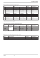

Index
!
2-point correction............21
A
Accessory equipment..........25
Additional alarms............12
Alarm handling ..........11-12
B
BlueControl...............24
C
Calibration level ..........21-23
Certifications ..............27
Configuration level ........14-17
Connecting diagramm ..........5
Connecting example ...........6
Current signal measuring range ....26
D
Digital input di1
Configuration ..........16
Technical data ..........26
E
Engineering tool ............17
Environmental conditions .......27
Error list ................10
Error status ...............11
Extended operating level .......8-9
F
Front view ................7
H
Housing .................27
I
Input INP1
Configuration ..........15
Parameter setting ........19
Technical data ..........26
Input scaling ..............20
L
LC alarm ................11
LED
°C.................7
°F.................7
Err-LED.............7
LED colours............7
M
Maintenance manager .........10
Method of operation limit value LC . . 11
Mounting.................4
O
Offset correction ............21
Output OUT1
Configuration ..........16
Technical data ..........26
Output OUT2
Configuration ..........16
Technical data ..........26
P
Parameter setting level ......18-20
Power supply ..............26
R
RESET key................7
Resetting to factory setting .......31
Resistance thermometer measuring range
.....................26
S
Safety hints ............29-31
Safety switch...............4
Setting of limit value LC .......8-9
T
Thermocouple measuring range ....26
V
Versions ................25
Voltage signal measuring range ....26
TB40-1 31