
Owner manual
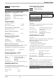

9 Technical data
INPUTS
PROCESS VALUE INPUT INP1
Resolution: > 14 bits
Decimal point: 0 to 3 digits behind the decimal point
Dig. input filter: adjustable 0,000...9999 s
Scanning cycle: 100 ms
Measured value
correction:
2-point or offset correction
Thermocouples
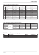
r Table 1 (page 27 )
Input resistance: ³ 1MW
Effect of source resistance: 1 mV/W
Cold-junction compensation
Maximal additional error: ± 0,5 K
Sensor break monitoring
Sensor current: £1 mA
Configurable output action
Resistance thermometer
r Table 2 (page 27 )
Connection: 2 or 3-wire
Lead resistance: max. 30 Ohm
Input circuit monitor: break and short circuit
Special measuring range
BlueControl (engineering tool) can be used to
match the input to sensor KTY 11-6
(characteristic is stored in the controller).
Physical measuring range: 0...4500 Ohm
Linearization segments 16
Current and voltage signals
r Table 3 (page 27 )
Span start, end of span: anywhere within measuring range
Scaling: selectable -1999...9999
Linearization: 16 segments, adaptable with
BlueControl
Decimal point: adjustable
Input circuit monitor: 12,5% below span start (2mA, 1V)
CONTROL INPUT DI1
Configurable as switch or push-button!
Connection of a potential-free contact suitable
for switching “dry” circuits.
Switched voltage: 2,5 V
Current: 50 mA
GALVANIC ISOLATION
Safety isolation
Function isolation
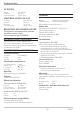
OUTPUTS
OUTPUT OUT LC
Function:
Interruption of the power supply if the set limit
is exceeded or fallen short.
Contact type: potential-free changeover contact
Max.contact rating: 500 VA, 250 V, 2A at 48...62 Hz,
resistive load
Min. contact rating: 5V, 10 mA AC/DC
Operating life (electr.): 600.000 duty cycles with max.
contact rating
OUTPUTS OUT1, OUT2
Function:
Additional alarms with MAX, MIN or MAX+MIN
monitoring with adjustable hysteresis.
Monitored signals:
w
process value (absolut)
w
difference to the limit (relative)
w
sensor break / short circuit
According to the input type, the input signal is
monitored to sensor break, polarity error and
short circuit
Contact type: 2 NO contacts with common
connection
Max. contact rating: 500 VA, 250 V, 2A at 48...62 Hz,
resistive load
Min. contact rating: 6V, 1 mA DC
Operating life (electr.): 800.000 duty cycles with max. rating
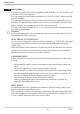
Note:
If the relays OUT1...OUT LC operate external
contactors, these must be fitted with RC
snubber circuits to manufacturer specifications
to prevent excessive switch-off voltage peaks.
POWER SUPPLY
Dependent of order
Technical data
TB40-1 25
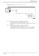
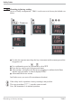
Power supply connections Process value input INP1
Digital input di1
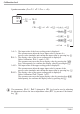
Relay outputs OUT 1,2
Relay output OUTLC