
Instruction Manual

rnG
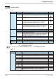
Name Value range Description Default
rnG.L
-1999...9999
Set-point limit low for set-point LC
-1999
rnG.H
-1999...9999
Set-point limit high for set-point LC
9999
g
Resetting the device configuration to factory setting (Default)
r chapter 10.1 (page 30)
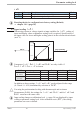
5.3 Input scaling InP.1
When using current or voltage signals as input variables for InP.1 scaling of
input and display values at parameter setting level is required. Specification of
the input value for lower and higher scaling point is in the relevant electrical unit
(mA/ V).
g
Parameters InL.1 , OuL.1, InH.1 and OuH.1 are only visible if
ConF / InP.1 / Corr = 3 is chosen.
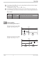
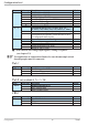
S.tYP Input signal InL.1 OuL.1 InH.1 OuH.1
30
(0...20mA)
0…20mA 0 any 20 any
4…20mA 4 any 20 any
40
(0...10V)
0…10V 0 any 10 any
2…10V 2 any 10 any
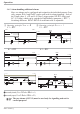
In addition to these settings, InL.1 and InH.1 can be adjusted in the range
(0...20mA / 0...10V) determined by selection of S.tYP .
a
For using the predetermined scaling with thermocouple and resistance
thermometer (Pt100), the settings for InL.1 and OuL.1 and for InH.1 and
OuH.1 must have the same value.
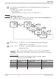
g
Input scaling changes at calibration level (r page 20) are displayed by input
scaling at parameter setting level. After calibration reset (OFF), the scaling
parameters are reset to default.
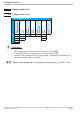
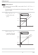
Parameter setting level
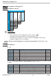
TB40-1 19 Input scaling InP.1
mA/V
phys.
quantity
mA / V
phys. quantity
OuH.x
OuL.x
InH.x
InL.x