PMA Prozeß- und Maschinen-Automation GmbH Temperature limiterTB 40-1 TB40-1 TB40-1 Operating manual English 9499-040-93411 Valid from: 8505
û BlueControl More efficiency in engineering, more overview in operating: The projecting environment for the BluePort® controllers on ! s ON ate I pd de T N U e. E and nlin D T ATrsion ma-o A-C e .p PM V ni ww r on i M w o Description of symbols in the text: on the device: g General information a Follow the operating instructions a General warning l Attention: ESD-sensitive devices © PMA Prozeß- und Maschinen-Automation GmbH • Printed in Germany All rights reserved.
Contents 1 2 2.1 Mounting . . . . . . . . . . . . . . . . . . . . . . . . . . . . . . 4 Electrical connections . . . . . . . . . . . . . . . . . . . . . . . 5 Connecting diagram TB 40-1 temperature limiter TB . . . . . . . 5 2.1.1 Terminal connection . . . . . . . . . . . . . . . . . . . . . . . . . . . 5 2.2 3 3.1 3.2 3.3 3.4 3.5 3.6 Connecting diagram TB 40-1 temperature monitor TW . . . . . . 7 Operation. . . . . . . . . . . . . . . . . . . . . . . . . . . . . . 8 Front view. . . . . . . . . . . .
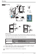
Mounting ) 4" ) 11 ( 1 2 LC OK 126 96 (3.78") +0,8 8 5" 6 4. (0 1. .0 .1 4. 0 .0 .4 ") (0 125 45 °C °F max. 60°C min. 0°C max. 95% rel. % 92 . 10 (3.62" +0.03) min.48 (1.89") 1 Mounting +0,6 (1.77" +0.02) Err RESET TB 40-1 universal 48 (1.89") Loc 10V i mA/Pt Loc 10V mA/Pt Safety switches Ü mA/Pt Loc Loc 10V 10V mA/Pt or: Ü * * Safety switch: For access to the safety switches, the controller must be withdrawn from the housing.
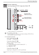
Electrical connections 2 Electrical connections 2.1 Connecting diagram TB 40-1 temperature limiter TB 1 2 90...250V 24V AC/DC L N 3 4 5 6 Zusatzkontakt / Additional contact OUT1 OUT2 Abschaltfunktion Interrupt function 7 8 LC 9 10 11 12 di1 13 mA 14 V* INP1 15 * g Safety switch mA i V in position left The controller is fitted with - flat-pin terminals 1 x 6,3mm or 2 x 2,8mm according to DIN 46 244 or - screw terminals from 0,5 to 2,5mm². 2.1.
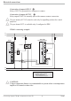
Electrical connections Connection of output OUT LC 4 Relay (250V/2A), potential-free changeover contact Connection of outputs OUT1/2 5 Relay outputs 250V/2A normally open with common contact connection pre-alarms (OUT1/2) must be used only for signalling and not for control a The purposes! a The pre-alarm OUT2 is available only if configured as TW! TB40-1 connecting example: L1 L2 fuse fuse KS 40-1 1 1 2 2 contactor 3 3 4 4 5 5 6 Logic fuse TB 40-1 1 Temperature limiter 7 8 6 SSR _ 7 8
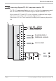
Electrical connections 2.2 Connecting diagram TB 40-1 temperature monitor TW The TB 40-1 temperature limiter can also be configured as temperature monitor. The connection of the 2nd thermocouple is omitted (terminals 12 –13). Relay contacts OUT1 and OUT2 can be configured as additional limit outputs and connected according to the connecting diagram below. Limit contact LC also is also connected according to the connecting diagram below. 1 2 90...
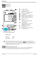
Operation 3 Operation 3.1 Front view 1 1 2 1 2 LC OK 126. 125 ! °C °F Err 2 3 5 6 7 8 4 9 RESET " 0 3 4 5 6 7 8 9 0 ! " Status of limits Lim.2, Lim.
Operation 3.3 Behavior with sensor break/ measuring circuit error If a sensor break/ measuring circuit error is recognized, the process value display changes to FAIL and the Err-LED blinks. ( -> Page 11 chapter 3.5 maintenance manager/ error list). All configured alarm limts are handled as exceeded, the appropriate Outputs are switched. The OK-LED ceases and the LC Output is opened. 3.
Operation 3.5 Maintenance manager / Error list With one or several errors, the extended operating level always starts with the error list. Signalling an actual entry in the error list (alarm, error) is done by the Err LED in the display. To reach the error list press Ù twice.
Operation g g Saved alarms (Err-LED is lit) can be acknowledged and deleted with the digital input di1 or the RESET-key. Configuration, see page : ConF / LOGI / Err.r If an alarm is still valid that means the cause of the alarm is not removed so far (Err-LED blinks), then other saved alarms can not be acknowledged and deleted.
Operation 3.6.2 Alarm handling additional alarms Max. two alarms can be configured and assigned to the individual outputs. Generally, outputs OuT.1and OuT.2 can be used each for alarm signalling. Each of the 2 limit values Lim.2 and Lim.3 has 2 trigger points H.2/ H.3 (Max) and L.2 / L.3 (Min), which can be switched off individually (parameter = “OFF”). Switching difference HYS.2/ HYS.3 of each limit value is adjustable. Ü Operaing principle Src.x = 0 L.1 = OFF InL.1 * Operaing principle Src.x = 1 L.
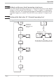
Operation g The variable to be monitored can be selected seperately for each alarm via configuration The following variables can be monitored: w process value w control deviation xw (process value - LC limit ( LC )) 3.7 Operating structure After supply voltage switch-on, the controller starts with the operating levels. The controller status is as before power off. 126 Ù 125 3 sec.
Configuration level 4 Configuration level 4.1 Configuration survey È Fnc.1 StYP O.Act O.Act Err.r Unit Ì Fnc.2 S.Lin dP Src.2 Corr Fnc.3 Src.3 g End Othr Display LOGI Digital inputs OUt.3 Output 3 OUt.2 Output 2 InP.1 Input 1 Lim Limit value functions ConF Configuration level diSP Adjustment: w The configuration can be adjusted by means of keys ÈÌ . w Transition to the next configuration is by pressing key Ù .
Configuration level 4.2 Configuration Lim Name Fcn.1 Value range Description Function of limit 1 5 Measured value monitoring upper limit (no latching) 6 Default 7 TW 1 TW Measured value monitoring lower limit (no latching) 7 Measured value monitoring + latching of the alarm status of the upper limit. A latched alarm can be reset by the error list, the digital input or the RESET-key (-> LOGI/ Err.r). 8 Measured value monitoring + latching of the alarm status of the lower limit.
Configuration level Name Value range Description Default 20 Pt100 (-200.0 ... 100,0 °C) 21 Pt100 (-200.0 ... 850,0 °C) 22 Pt1000 (-200.0 ... 850.0 °C) 23 special 0...4500 Ohm (preset to KTY11-6 ) 24 special 0...450 Ohm 30 0...20mA / 4...20mA 1 40 0...10V / 2...10V 1 0 S.Lin Linearization (only at S.tYP = 23 (KTY 11-6), 24 (0...450W), 30 (0..20mA), 40 (0..10V) and 41 (0...100mV) ) 0 none 1 Linearization to specification. Creation of linearization table with engineering tool possible.
Configuration level othr Name Value range Description Unit 0 without unit 1 °C 2 °F dP Decimal point (max. number of digits behind the decimal point) 0 No digit behind the decimal point 1 1 digit behind the decimal point 2 2 digits behind the decimal point 3 3 digits behind the decimal point diSP Type of measured value display 0 No measured value display 1 Full display resolution 2 Display resolution: 2 digits 3 Display resolution: 5 digits 4 Display resolution: 10 digits 0..200 C.
Parameter setting level 5 Parameter setting level 5.1 Parameter survey End rnG LC setting range È LC Ì L.2 InP.1 Input 1 Lim Limit value functions PArA Parameter setting level InL.1 rnGL OuL.1 rnGH H.2 InH.1 HYS.2 OuH.1 L.3 tF.1 H.3 HYS.3 g Adjustment: w The parameters can be adjusted by means of keys ÈÌ w Transition to the next parameter is by pressing key Ù w After the last parameter of a group, donE is displayed, followed by automatic change to the next group.
Parameter setting level rnG Name rnG.L rnG.H g Value range Description -1999...9999 Set-point limit low for set-point LC -1999...9999 Set-point limit high for set-point LC Default -1999 9999 Resetting the device configuration to factory setting (Default) r chapter 10.1 (page 30) 5.3 Input scaling InP.1 When using current or voltage signals as input variables for InP.1 scaling of input and display values at parameter setting level is required.
Calibration level 6 Calibration level g Measured value correction ( CAL) is only visible if ConF / InP.1 / Corr = 1 or 2 is chosen. The measured value can be matched in the calibration menu ( CAL). Two methods are available: Offset correction ( ConF/ InP.1 / Corr =1 ): display standard setting offset correction w possible on-line at the process OuL.1new OuL.1old InL.1 X 2-point correction ( ConF/ InP.
Calibration level Offset correction ( ConF/ InP.1 / Corr =1 ): r 126 125 °C °F Err r Ù r PArA 3 sec. Ì : CAL r Ù r InP.1 r Ù r InL.1 r Ù r OuL.1 È r Ù Ì r End r Ù InL.1: The input value of the scaling point is displayed. The operator must wait, until the process is at rest. Subsequently, the operator acknowledges the input value by pressing key Ù. OuL.1: The display value of the scaling point is displayed. Before calibration, OuL.1 is equal to InL.1.
Calibration level 2-point correction ( ConF/ InP.1 / Corr = 2): r 126 r Ù r 125 °C °F Err 3 sec. PArA Ì : CAL r Ù r InP.1 r Ù r InL.1 r Ù r OuL.1 È r Ù Ì r InH.1 r Ù r OuH.1 È r Ù Ì r End r Ù InL.1: The input value of the lower scaling point is displayed. The operator must adjust the lower input value by means of a process value simulator and confirm the input value by pressing key Ù. OuL.1: The display value of the lower scaling point is displayed. Before calibration, OuL.1 equals InL.1.
BlueControl 7 BlueControl BlueControl is the projection environment for the BluePort â controller series of PMA. The following 3 versions with graded functionality are available: The mini version is - free of charge - at your disposal as download at PMA homepage www.pma-online.de or on the PMA-CD (please ask for). At the end of the installation the licence number has to be stated or DEMO mode must be chosen. At DEMO mode the licence number can be stated subsequently under Help r Licence r Change.
Versions 8 Versions 000 TB4 0 1 Flat pin connectors Screw terminal connectors 0 1 1) 90..250V AC, 3 relays, TW 0 1) 24VAC / 18..30VDC, 3 relays, TW 1 2) 90..250V AC, 2 relays, TB 2 2) 24VAC / 18..30VDC, 2 relays, TB 3 Standard configuration Configuration to specification No manual Manual German Manual English Manual French Standard CE-certified) cULus certified (with screw terminals only!) 0 9 0 D E F 3) EN14597 certified (replaces DIN 3440) Standard version Customer specification 0 U D 00 ..
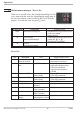
Technical data 9 Technical data CONTROL INPUT DI1 INPUTS PROCESS VALUE INPUT INP1 Resolution: Decimal point: Dig. input filter: Scanning cycle: Measured value correction: > 14 bits 0 to 3 digits behind the decimal point adjustable 0,000...9999 s 100 ms 2-point or offset correction Thermocouples r Table 1 (page 27 ) If the device is used as a teperature limiter, a double thermocouple must be connected.
Technical data Contact type: 2 NO contacts with common connection Max. contact rating: 500 VA, 250 V, 2A at 48...62 Hz, resistive load Min. contact rating: 6V, 1 mA DC Operating life (electr.): 800.000 duty cycles with max. rating Note: If the relays OUT1...OUT LC operate external contactors, these must be fitted with RC snubber circuits to manufacturer specifications to prevent excessive switch-off voltage peaks.
Technical data Mounting Panel mounting with two fixing clamps at top/bottom or right/left. High-density mounting possible Mounting position: Weight: uncritical 0,27kg Accessories delivered with the unit Operating manual Fixing clamps Table 1 Thermocouple measuring ranges Type L J K N S R T C D E B* Fe-CuNi (DIN) Fe-CuNi NiCr-Ni Nicrosil/Nisil PtRh-Pt 10% PtRh-Pt 13% Cu-CuNi W5%Re-W26%Re W3%Re-W25%Re NiCr-CuNi PtRh-Pt6% Range -100...900°C -100...1200°C -100...1350°C -100...1300°C 0...1760°C 0...
Safety hints 10 Safety hints definition according to EN 14597 (former DIN 3440) + Modified “Temperature control devices and temperature limiters for heat generating systems” After introduction of this new standard (2005-12) the definitions described therein were changed again.
Safety hints w If the controller is connected with other units in the same signal loop, check that the equipment in the output circuit is not affected before switch-on. If necessary, suitable protective measures must be taken. w The unit may be operated only in installed condition. w Before and during operation, the temperature restrictions specified for controller operation must be met.
Safety hints 10.1 Resetting to factory setting In case of faulty configuration, TB40-1 can be reset to ist factory the default condition. 1 2 3 4 5 ÌÈ + Power on È Ù FAC torY FAC °C °C YES °F Err °F Err FAC PASS °C °F Err 1. FAC no FAC °C °F COPY Err 8.8.8.8. °C 8.8.8.8. 5 °F Err For this, the operator must keep the keys increment and decrement pressed during power-on: È 2 3 4 °F Err 2. 1 °C Ì For confirmation, press key increment to select YES.
Index ! 2-point correction. . . . . . . . . . . . 20 A Accessory equipment . . . . . . . . . . 24 Additional alarms. . . . . . . . . . . . 12 Alarm handling . . . . . . . . . . 11 - 12 B BlueControl. . . . . . . . . . . . . . . 23 C Calibration level . . . . . . . . . . 20 - 22 Certifications . . . . . . . . . . . . . . 26 Configuration level . . . . . . . . 14 - 17 Connecting diagramm . . . . . . . . 5 - 6 Connecting example . . . . . . . . . . . 6 Current signal measuring range . . . .
Subject to alterations without notice Änderungen vorbehalten Sous réserve de toutes modifications © PMA Prozeß- und Maschinen-Automation GmbH P.O.B.