
Manual


.
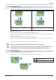
5 Operation
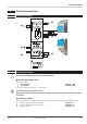
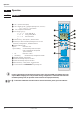
5.1 Front view
1 Line 1: process value display
2 Line 2: display of unit / extended operating level / error list /
Conf and PArA level values
3 Tare / sample & hold activated
4 Error list (2 x ô ), e.g.
· Fbf. x sensor fault INP. X
· Pol. x wrong polarity INP. X
· Lim. x limit value alarm
· ...
5 Increment key / "slave pointer", maximum value
6 Enter key to select extended operating level or error list
Parameter-, Konfigurations-, Installations-Ebene
7 Status indicator LEDs
· green: limit value 1 OK
· green blinking: no data exchange with bus coupler
(only on instruments with optional
system interface)
· red: limit value 1 active
· red blinking: instrument fault, configuration mistake
8 Display elements, active as bars
9 Status of switching output OUT1 active
0 Status of switching output OUT2 active
! Decrement key/ "slave pointer", minimum value
§ PC connection for the BlueControl
Ò
engineering tool
g
In the first LCD-display line the measured value is shown. The second LCD-line normally shows the
setpoint. When changing over to the parameter setting, configuration or calibration level and at the
extended operating level, the parameter name and value are displayed alternately.
+
§ : To facilitate withdrawal of the PC connector from the instrument, please, press the cable left.
Operation
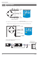
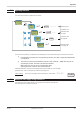
17 Front view SG 45
+SENSE-
+ INP -
EX+
EX-
2
kg
SG